Basics of Mixing – 9.4 Tape Saturation

Hello! I’m Jooyoung Kim, a mixing engineer and music producer.

Today’s topic is tape saturation. This content is based on my Korean book, Basics of Mixing.

Let’s get started!

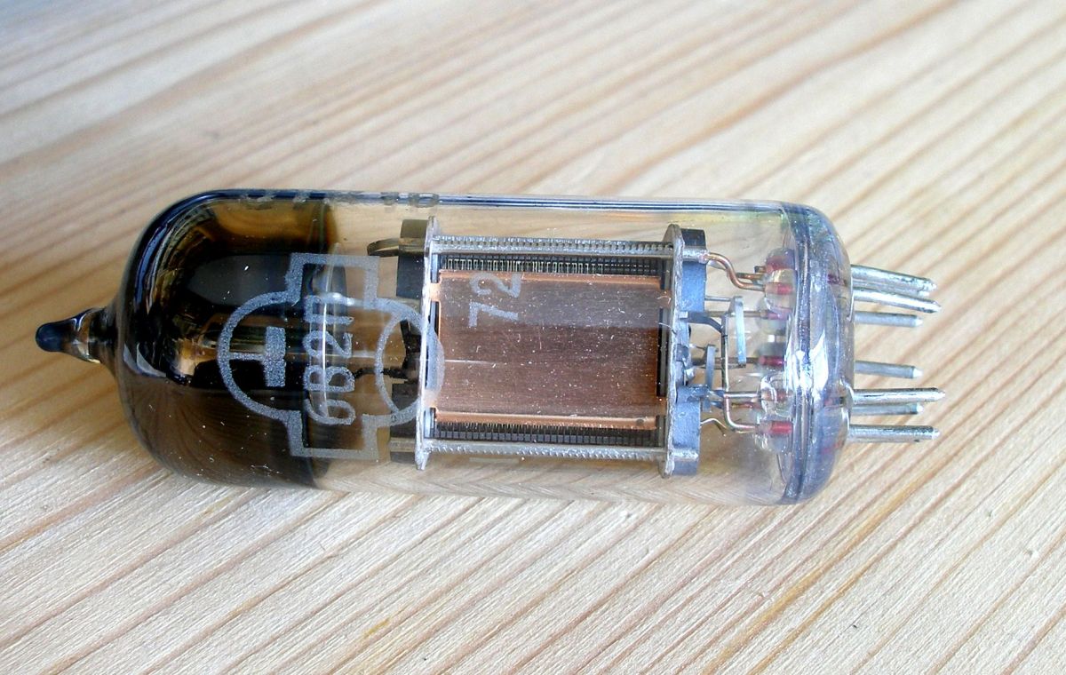
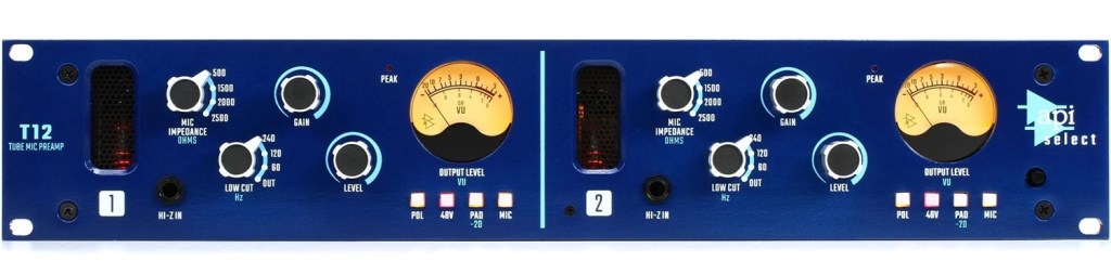
Before CDs, tape was the main storage medium, recording sound through magnetic properties. There was even digital tape during the transition from analog to digital. Tape’s unique magnetic characteristics create distinct audio qualities.

Hysteresis Loop

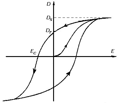
Do you remember playing with magnets and needles as a kid? If you rubbed a needle with a magnet and then removed it, the needle retained some of the magnet’s properties. This phenomenon, where output doesn’t completely disappear even when the input stops, is called hysteresis.

In tape recording, hysteresis causes non-linear recording, meaning quiet sounds are recorded even quieter. This is a fascinating trait unique to tape.

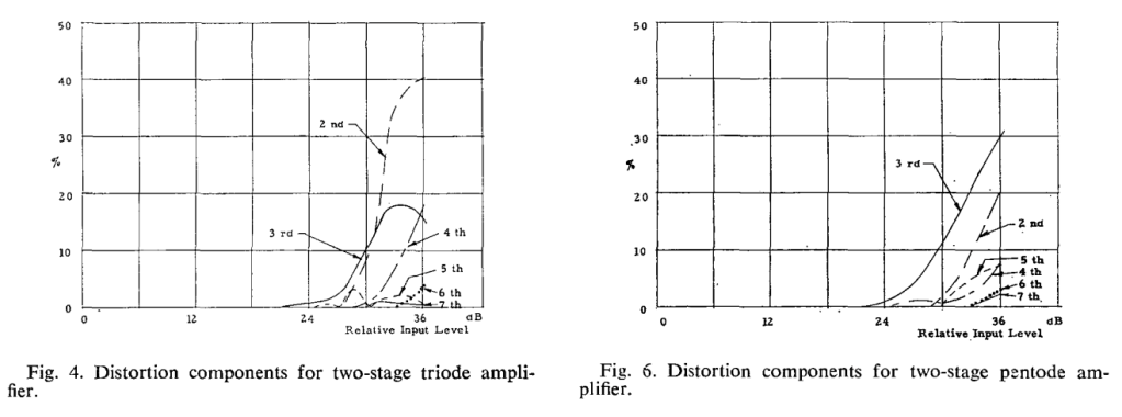
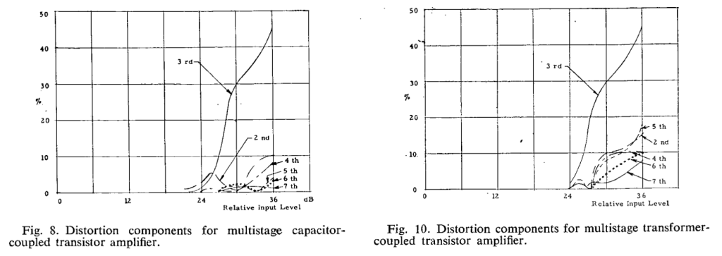
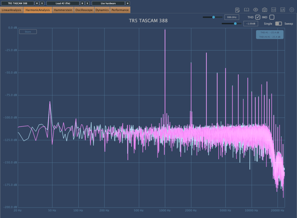
Mixing Basics – 9.1 Harmonics and Saturation – I previously discussed how non-linear outputs inevitably produce harmonic distortion.

Additionally, because quiet sounds are recorded even quieter, a high-frequency tone (bias) is added, increasing sound pressure to prevent this quieting effect.

The Tape Head and Other Characteristics

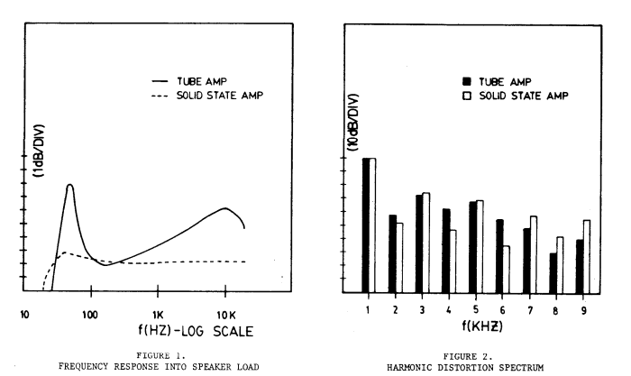
The tape head has a very narrow gap. Sounds with wavelengths smaller than this gap (i.e., higher frequencies) cannot be recorded accurately, causing high frequencies to roll off.

Over time, other tape-specific effects emerge: pitch variation due to tape stretch, wow and flutter noise from tape movement and dust, among others.

All these factors create tape’s unique saturation characteristics.

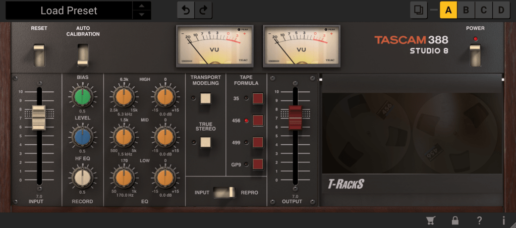
This is why tape plugins often include frequency response, harmonic distortion, and other distinctive features. Some plugins even emphasize high frequencies unexpectedly.

So why use tape? Simply put, it sounds good! Understanding these characteristics also helps in adjusting plugin parameters effectively.

That’s all for today. See you in the next post!

Basics of Mixing – 9.2 Saturation of Transistors and Vacuum Tubes

Hello, I’m Jooyoung Kim, an audio engineer and music producer. I’ve been quite busy lately, and my blog posts have been delayed…^^;;

Today, I want to talk about the saturation effects of transistors and vacuum tubes.

Shall we get started?

First of all, why do we use transistors and vacuum tubes? Let’s start with this question. Why exactly are they used?

In the past, they were found in speakers, amplifiers, and even microphone preamps used by musicians—basically everywhere. The primary reason we use them is to “amplify” small electrical signals.

Now, I believe you understand why components like vacuum tubes or transistors are included in speaker power amps, integrated amps, microphone preamps, and why they are called “amps” in the first place.

In my previous post, “[Link – 9.1 Harmonics and Saturation],” I explained from a non-linear signal perspective why harmonics are produced when signals pass through these devices.

Let’s dive into how these harmonics are generated.

W. Bussey and R. Haigler, “Tubes versus transistors in electric guitar amplifiers,” ICASSP ’81. IEEE International Conference on Acoustics, Speech, and Signal Processing, Atlanta, GA, USA, 1981, pp. 800-803, doi: 10.1109/ICASSP.1981.1171205.

The image above is from a 1981 paper titled Tubes versus Transistors in Electric Guitar Amplifiers. It shows the response of electric guitar amps that use vacuum tubes or transistors.

The graph on the left shows the frequency response, while the one on the right displays harmonic distortion. It’s clear how different they are, even without further explanation.

References
O., H. R. (1973). Tubes Versus Transistors – Is There an Audible Difference? Journal of the Audio Engineering Society, 21, 267–273.

If you search online for Tubes Versus Transistors – Is There an Audible Difference?, you’ll find this paper. It’s originally an AES paid article, so if there’s any issue with the image, I’ll remove it…^^;;

Anyway, the top left graph shows two triodes (vacuum tubes), and the top right shows two pentodes (vacuum tubes). The bottom left graph combines capacitors and transistors, while the bottom right combines transformers and transistors.

So, what is this measuring? It’s measuring harmonic distortion based on input level. Rather than focusing on specific meanings, it’s enough to note that they are all very different.

If each vacuum tube and transistor has different harmonic distortion characteristics, is it really meaningful to define sound solely based on whether it’s a tube or a transistor? In my view, it’s not that significant.

What’s important for music production, in my opinion, is not differentiating between these categories but understanding how each specific device affects sound individually.

This is a microphone preamp with a vacuum tube… Doesn’t it make sense that different brands of tube preamps have their own distinct characteristics?

As an equipment enthusiast, I find myself trying to understand each piece of gear one by one, and my bank account… well… haha… ha… ha…

To make matters worse, I also play instruments, so it’s quite the struggle… I’ve been hunting for a second-hand bass recently because I’ve decided to play bass myself. It looks like I’ll be carrying this gear addiction with me for the rest of my life.

That’s it for today. In the next post, I’ll discuss the saturation effects of tape 🙂