Advanced Synthesizers and Gear – (4) Modulations and Vocoder

Hello! This is Jooyoung Kim, an audio engineer and music producer.

Last post, we figured out the fundamental components of the modular synthesizer: VCO, VCF, and VCA. Today, I’ll talk about modulation , which is essential in various systems, including vocoder.

I have already written a few posts on modulation principles and related synthesizers—especially frequency modulation. Please read them first if you are not yet familiar with the basics of FM (Frequency Modulation), AM (Amplitude Modulation), PM (Phase Modulation), and RM (Ring Modulation).


Modulation

Although the PM graph in the AI-generated image contains some visual inaccuracies, the overall illustration still serves as a helpful conceptual guide when paired with the article.


So, what is modulation?

Essentially, it is the process of altering a parameter of one audio signal (Carrier) using another (Modulator). This creates a temporal cycle, which produces more complex and evolving timbres.

For instance, we can modulate a signal’s amplitude, frequency, or phase; these methods are known as AM, FM, and PM, respectively.

How about ring modulation?

Since Gemini kept glitching, I just had it generate the Python code and tweaked it myself to make this chart..:)

At first glance, Ring Modulation’s (RM) waveform appears highly similar to that of Standard AM. However, a closer look reveals distinct differences, particularly at the null points (zero-crossing points). While Standard AM exhibits no phase inversion, Ring Modulation instantly flips the phase of the carrier signal by 180° every time the modulator crosses the zero axis.

In Standard AM, the unmodulated carrier component is always present because the modulator operates with a positive DC offset. As a result, the waveform’s envelope simply scales down to a null point at its lowest peak and expands back up, maintaining a perfectly continuous phase alignment.

Ring Modulation, conversely, is a form of suppressed-carrier transmission. Without a DC offset, the carrier is completely wiped out whenever the modulator hits zero. The moment the modulating signal goes negative, the carrier wave inside the envelope mirrors itself upside down.

This constant, rapid flipping completely destroys the original harmonic structure of the sound. Instead of creating musical, harmonic overtones, it introduces harsh, non-harmonic, and metallic sidebands.

Buchla & Tiptop Audio Model 258t

Additionally, you can easily find these modulation functions built directly into various VCO modules as well. For instance, the Buchla & Tiptop Audio Model 258t panel shown in the figure above features an FM function with a 3.5mm input jack.

Vocoder

Arturia Minifreak Vocoder

Even though both the Vocoder and the Talkbox (Vox Box) use the human voice to shape sound, their underlying principles are entirely different. In a vocoder, the human voice functions as a modulator that controls the amplitude of a carrier signal—essentially acting as a multi-band AM system.

MXR Talk Box

On the other hand, a Talkbox uses the physical structure of the human mouth to filter the original instrument sound. It behaves like a dynamic formant filter—a concept I will dive into deeper in a future post—emphasizing specific frequency bands as the performer shapes their mouth to speak.

n recent years, vocoders have transitioned into convenient virtual instruments that are incredibly easy to integrate into any modern DAW. To help you get started, here are some of the most acclaimed vocoder plugins on the market today.

(The links below are affiliated with Plugin Boutique, meaning I may earn a small commission at no extra cost to you if you decide to make a purchase—your support keeps this blog running!)

Behringer Vocoder VC16

What’s more, vocoder modules exist in modular synthesizer systems as well like Behringer VC16!


To be honest, I don’t usually attach sound examples in my posts—embedding audio into a blog takes a serious amount of time and effort. That said, every modulation type has a completely different vibe. If you truly want to design your own sounds, you just have to dive in and get familiar with the unique sonic characteristics of each method.

That’s all for today. See you in the next post!

Advanced Synthesizers and Gear – (3) VCO, VCF, and VCA

Hello! I’m Jooyoung Kim, an audio engineer and music producer.

Today, I’d like to talk about the essential components of sound generation in a synthesizer. Every synthesizer or modular system utilizes these three core functions: the VCO, VCF, and VCA.

Their functions are explained below:

  • VCO (Voltage Controlled Oscillator): Generates basic waveforms such as sine, square, sawtooth, and triangle waves.
  • VCF (Voltage Controlled Filter): Processes the signal from the VCO by attenuating specific frequencies. Common types include low-pass, high-pass, and band-pass filters, which are essential for sound design.
  • VCA (Voltage Controlled Amplifier): Acts as a gate or gain stage that shapes the volume of the audio signal over time, typically controlled by an envelope generator (which defines the attack, decay, sustain, and release of the sound).

VCO – Basic Waveforms

Doepfer A-110-1 Standard VCO

You can easily find these waveforms on a VCO module. The image above is an example from Doepfer A-100 module system; the waveforms are depicted on the panel, located below the output connectors.

As you can see, there are four types of basic waveforms: sine, square (pulse), sawtooth, and triangle. They are created by combining various harmonics, which can be expressed using mathematical equations.

Therefore, I will explain all types of waveforms with graphs and equations.

Sine Wave

Sine wave is the most fundamental wave. It is defined by the function:

f(t)=Asin(ωt+ϕ)f(t) = A \sin(\omega t + \phi)
  • A: Amplitude (peak value)
  • ω: Angular frequency
  • ϕ: Phase shift
  • t: time

Square Wave

Square wave is a periodic wave that switches between two levels. It can be represented as an infinite summation of odd harmonics of sine waves:

f(t)=4Aπn=1,3,5,...1nsin(nωt)f(t) = \frac{4A}{\pi} \sum_{n=1,3,5,…}^{\infty} \frac{1}{n} \sin(n \omega t)
  • A: Amplitude (peak value)
  • ω: Angular frequency
  • t: time

Sawtooth Wave

This waveform increases linearly and drops instantly. It contains all integer harmonics:

f(t)=2Aπn=1(1)n+1nsin(nωt)f(t) = \frac{2A}{\pi} \sum_{n=1}^{\infty} \frac{(-1)^{n+1}}{n}{\sin(n \omega t)}
  • A: Amplitude (peak value)
  • ω: Angular frequency
  • t: time

Triangle Wave

It is similar to a sawtooth, but symmetric. It consists only of odd harmonics, but with a faster decay of amplitude:

f(t)=8Aπ2n=1,3,5,...(1)(n1)/2n2sin(nωt)f(t) = \frac{8A}{\pi^2} \sum_{n=1,3,5,…}^{\infty} \frac{(-1)^{(n-1)/2}}{n^2} \sin(n \omega t)
  • A: Amplitude (peak value)
  • ω: Angular frequency
  • t: time

Each waveform has distinctive sound characteristics, and these basic waves are the foundation of synthesizers.

As a side note, because the sawtooth wave contains the richest harmonics among these basic forms, it is frequently used to create pad sounds to fill up the background.


VCF – Basic Filters

Behringer 121 Dual VCF

Basic filters are typically categorized into three types: low-pass (high-cut), high-pass (low-cut), and band-pass. Filters have various parameters, but I will introduce only the basics today.

  • Cutoff Frequency: Due to the characteristics of the Butterworth filter (the standard filter used in audio), 3 dB of attenuation occurs at the cutoff frequency.
  • Slope: 6dB/oct is the fundamental slope. This represents one ‘pole’ of the filter. Since filter order (the number of poles) determines the steepness, you will commonly see slopes of 12, 18, 24 dB/oct, etc.

Many filter modules include a resonance function that emphasizes frequencies near the cutoff frequency. When modulated, the fluctuating cutoff frequency also causes the resonance peak to shift. This shifting creates the perception of pitch fluctuation, even though the actual fundamental pitch remains unchanged.


VCA – ADSR Envelope Generator

Although I have covered the ADSR concept previously, I will break it down again for those who are new to it. While a VCO and VCF are essential for creating and shaping a sound, they do not have a built-in gate mechanism to trigger or shape the signal’s output. This is where the ADSR envelope comes in.

ADSR stands for Attack, Decay, Sustain, and Release. These four parameters define how the amplitude of a signal changes over time as it passes through a VCA.

  • Attack (time): The time it takes for the sound to reach its peak level from the moment a key is pressed.
  • Decay (time): The time it takes for the sound to drop from its peak level to the designated sustain level.
  • Sustain (level): The volume level that the sound maintains while the key is held down.
  • Release (time): The time it takes for the sound to fade away completely after the key is released.
Behringer 182 sequencer

In modular synthesizers, sequencer modules are often used instead of keyboards.


So far, we have explored the essential building blocks of a synthesizer. These modules serve as the ‘alphabet’ of sound design; therefore, becoming familiar with them is crucial for mastering these complex musical instruments.

That’s all for today. I hope this overview helps, and I look forward to seeing you in the next post!

Manley Nu Mu Stereo Limiter/Compressor Review

Hello! This is Jooyoung Kim, an audio engineer and music producer.

Now that the semester is over, I have a few weeks to rest and prepare materials for my next classes. Even so, I still have a lot of work to do on my new research, my DIY hardware projects, and my English studies. It will be very busy holidays.


By the way, recently, I decided that I need to sell my compressors, the Heritage Audio Successor and the Stam Audio SA-4000 MK2, and replace them with a mastering-grade compressor to mix and master music better.

Fortunately, last week I sold both of them, and I have been happily considering which mastering-grade compressor I should buy. There were several options to choose from, but I finally decided to buy the Manley Nu Mu Stereo Limiter/Compressor.

This decision came from my experience with the SPL IRON, the SPL Venos, and the Chandler Limited RS660 compressors, which are vari-mu-style compressors. They sound great across many genres, but they aren’t within my budget. (If I bought them, I’d have to live on cup noodles for about three months! :))

I also had an experience with the original Neve 33609/C compressor/limiter and the Chandler Limited EMI TG12413 Zener Limiter. These are diode-bridge compressors that have really great saturation; however, they are also unaffordable.

I found two reasonably priced compressors: the Rupert Neve Designs 5254 Shelford Diode Bridge Compressor and the Manley Nu Mu Stereo Limiter/Compressor. I ultimately chose the Manley because it was more affordable. Also, having previously owned a diode-bridge compressor—the Heritage Audio Successor—I was ready to explore a different style.

I was also attracted to the WesAudio ngBusComp, which features a handy digital recall system. However, it is a VCA-style compressor, which is the same type as the Stam Audio SA-4000 MK2 that I used to own.

Therefore, I decided to buy the Manley Nu Mu Stereo Limiter/Compressor!


Build Features

The Manley Nu Mu features eight knobs, six buttons, and two switches, excluding the power switch. The knobs (Threshold, Output, Recovery (Release), and Attack) and switches (Input Level) on the left side are identical to those on the right, allowing for independent adjustment of the left and right signals.

The Link button couples the left and right signal control knobs, with the notable exception of the Output controls. Consequently, these must be matched manually via measurement. Furthermore, apart from the Recovery knob, all controls feature continuous rotation, which makes precise recall of previous settings difficult.

The HIP (High Impact Preservation) control compresses quieter sounds while leaving loud peaks untouched. It processes these signals internally to achieve results similar to parallel compression. I found that the audio sounds more natural when engaged, so I may leave this button on permanently.

The HP SC (Sidechain High Pass Filter) button activates an internal filter with a 100Hz corner frequency and a 6dB/octave slope. This prevents the compressor from reacting to low-frequency energy below 100Hz, ensuring more stable gain reduction.


Measurments

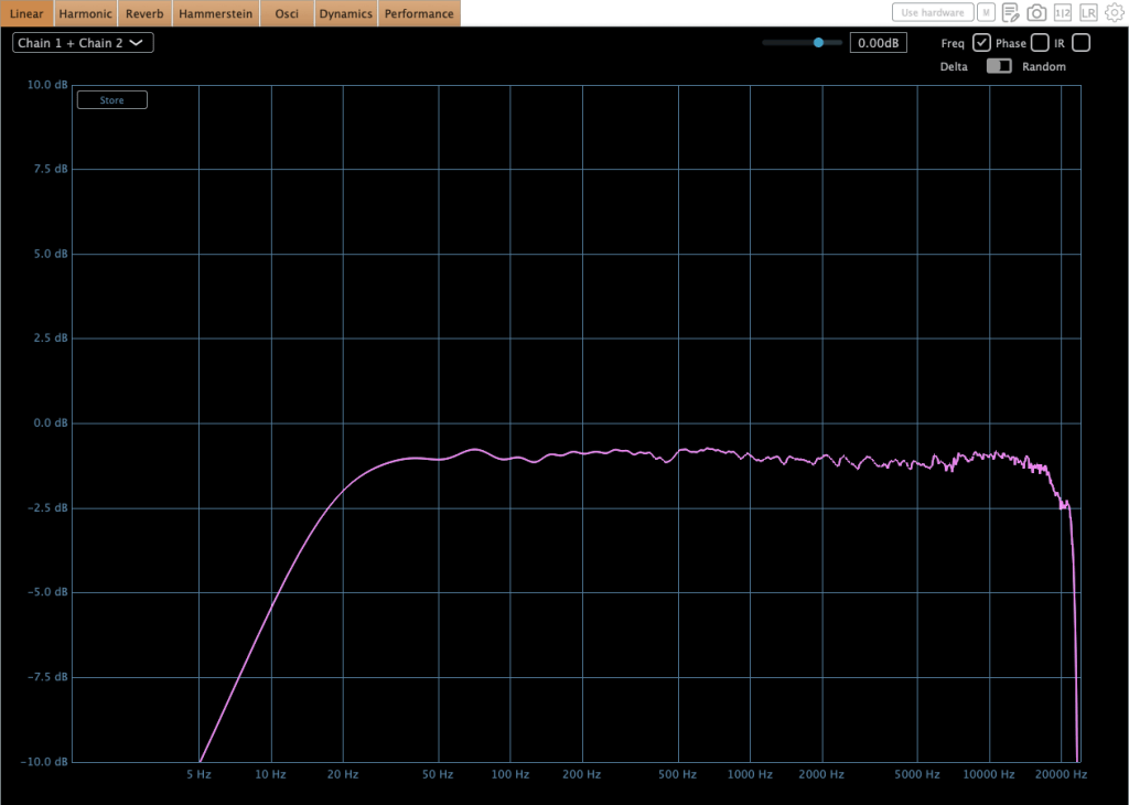
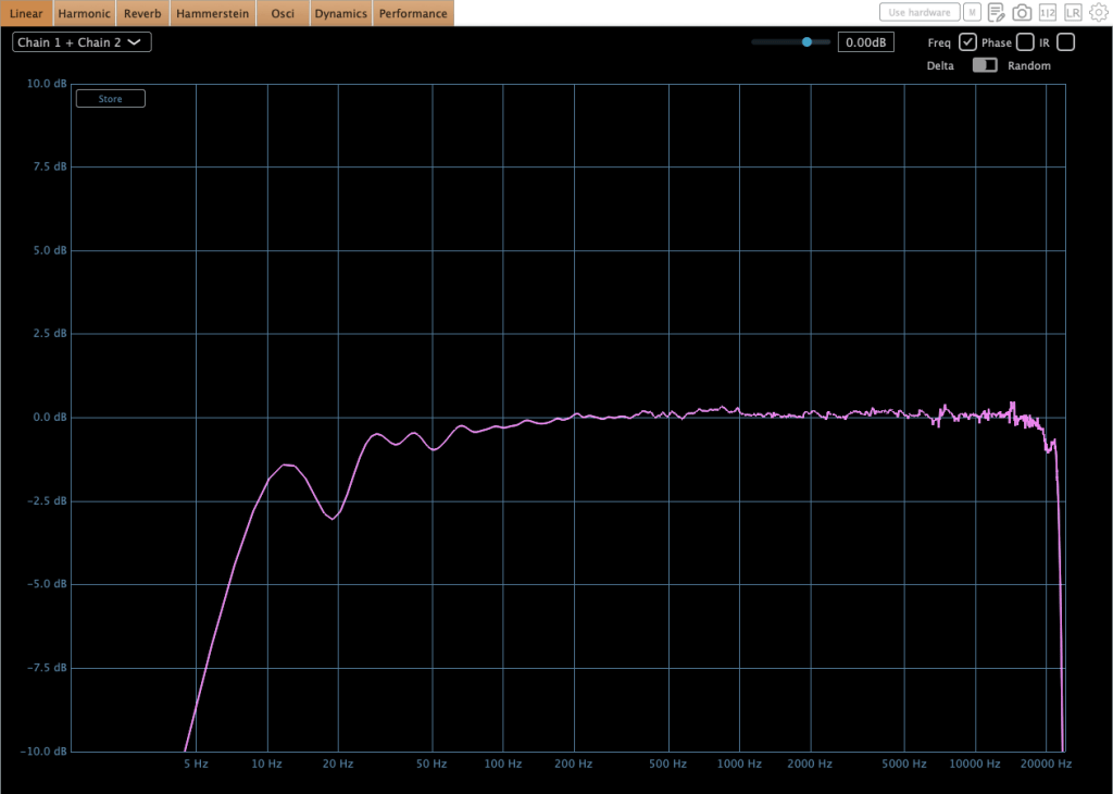
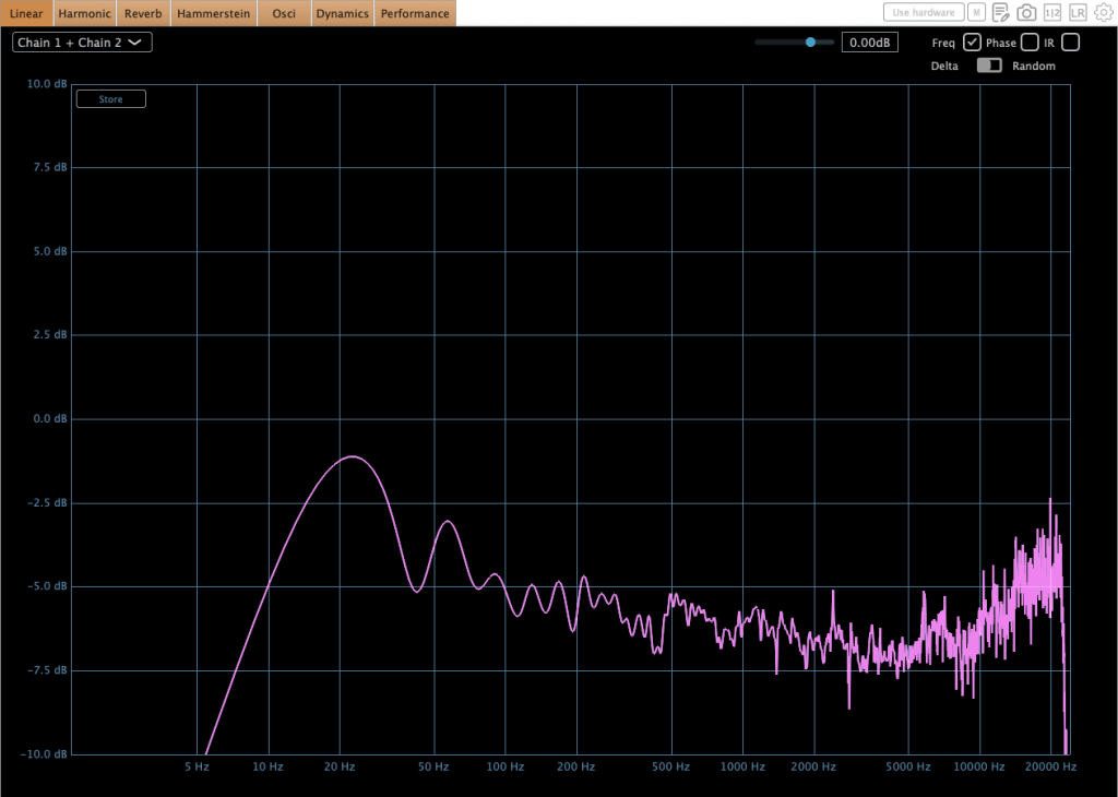
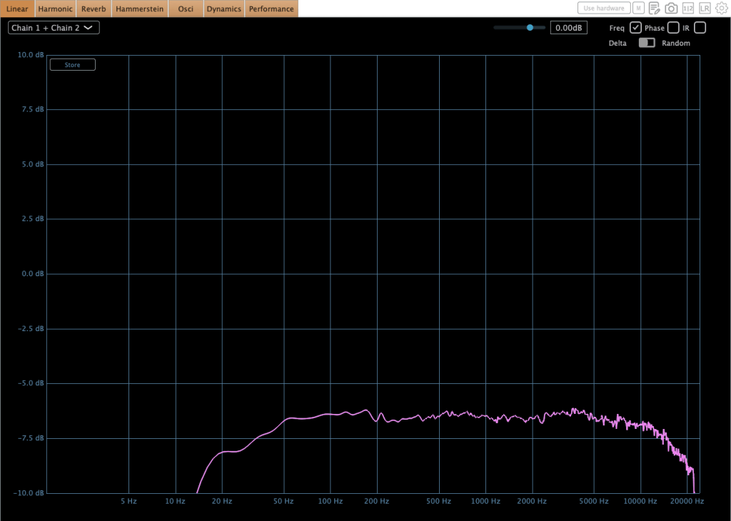
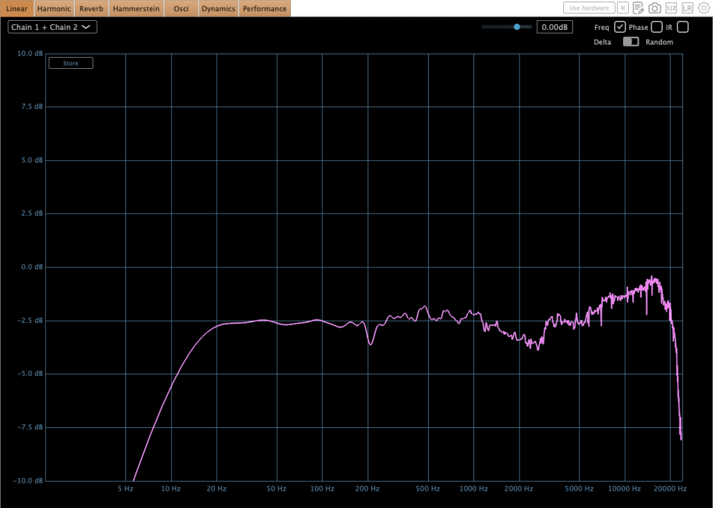
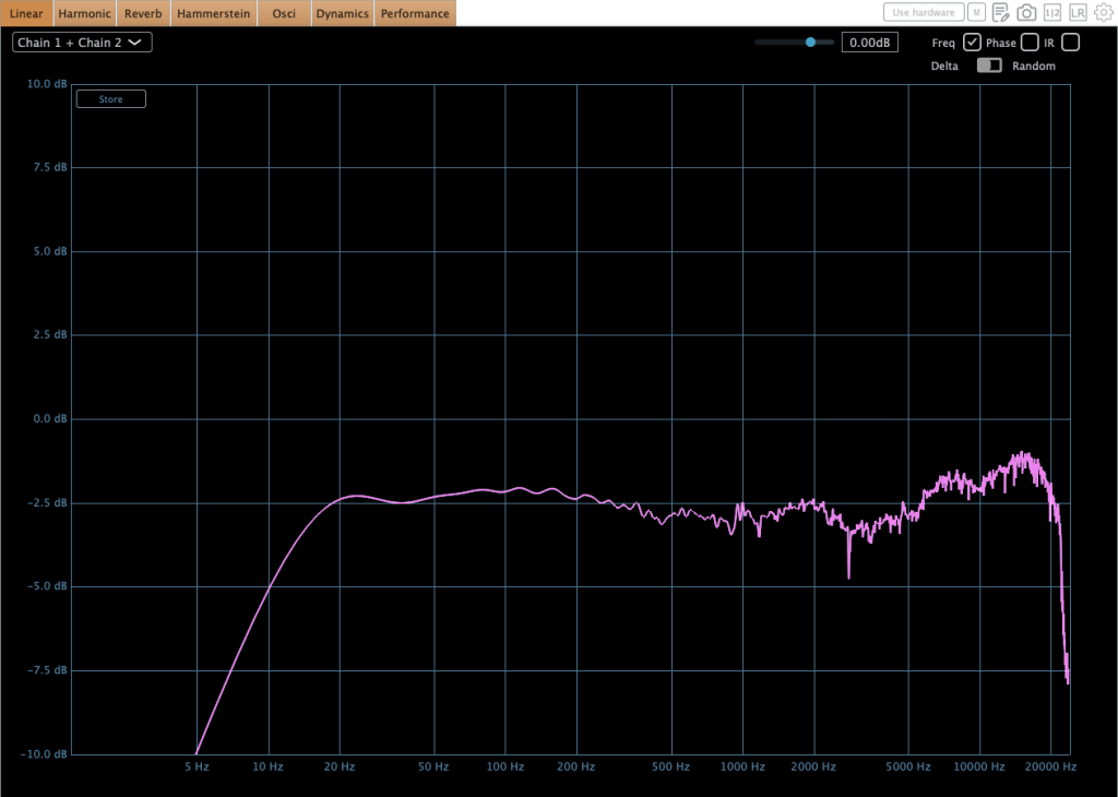
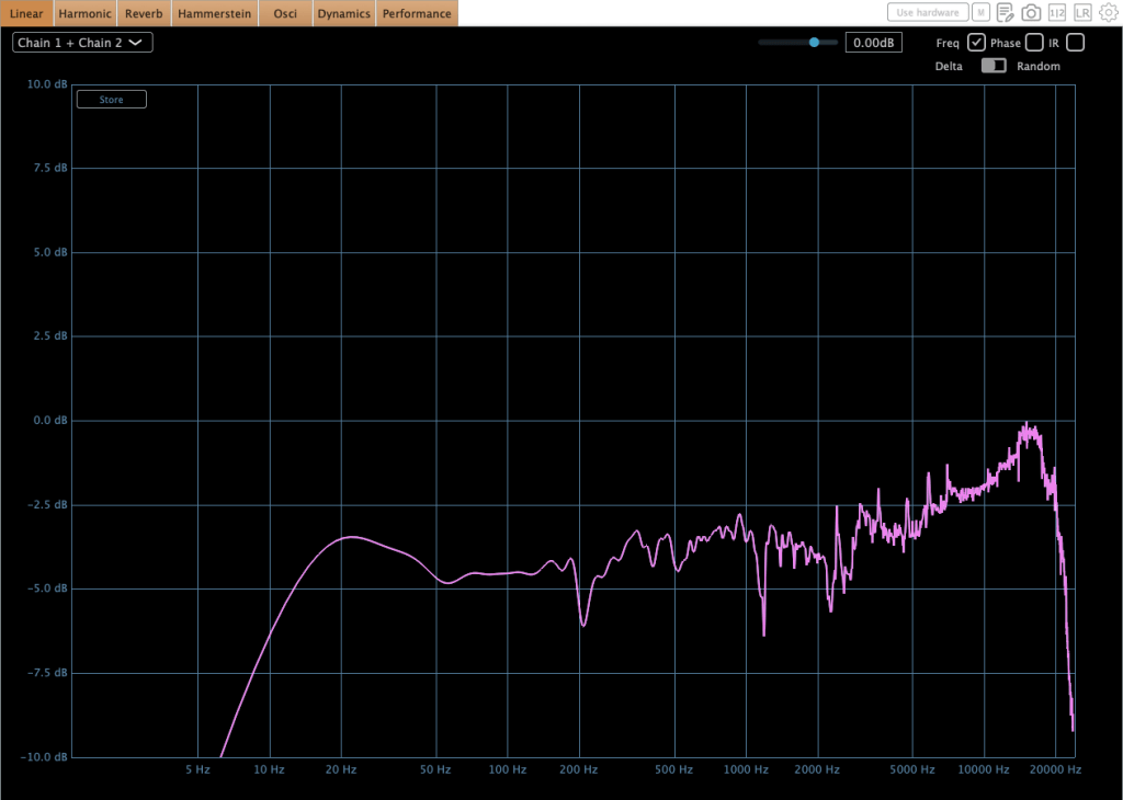
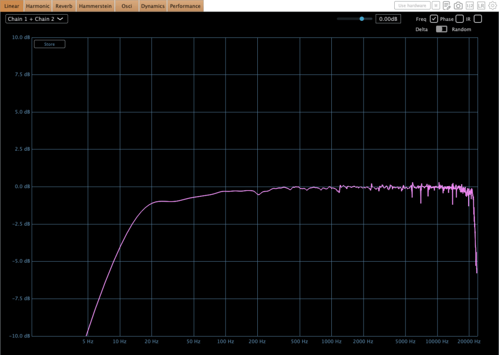
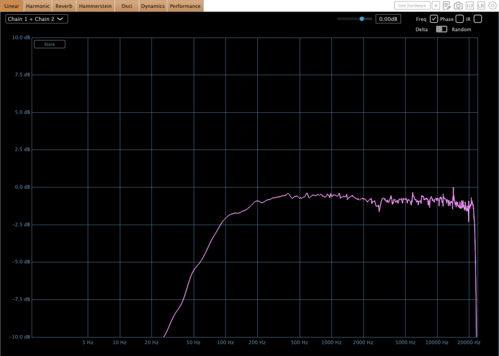
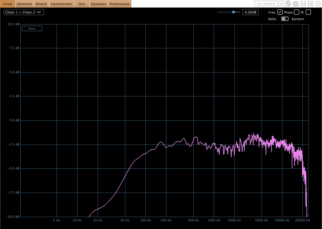
This equipment exhibits characteristic behaviors. Variations in input gain, threshold, attack time, and release time significantly affect the low-frequency response. Additionally, there is a slight amplitude discrepancy between the left and right circuits in the low end. This difference is easily observed in many compressors that do not naturally exhibit a low cut in their frequency response. For instance, when I demoed the SPL Venos, I found a significant discrepancy in the low-frequency output. Furthermore, an engineer peer of mine mentioned struggling with the same low-end inconsistency after purchasing an SPL Iron.

So, this level of discrepancy is acceptable.

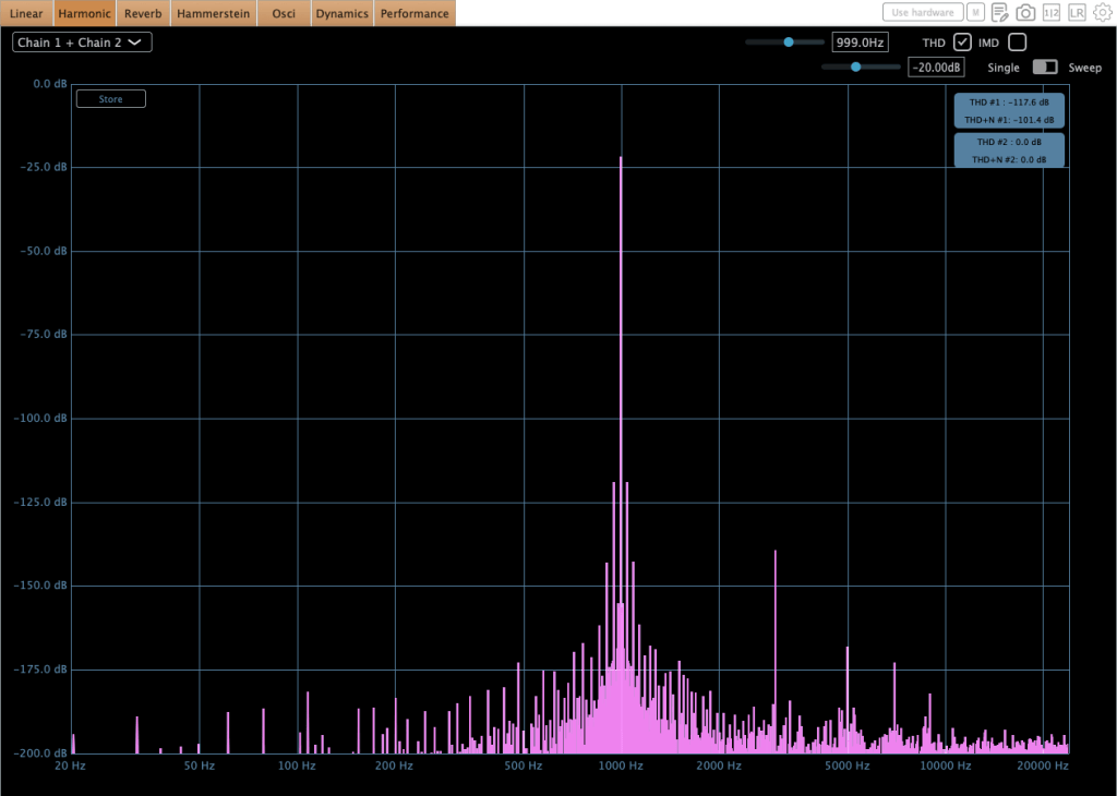
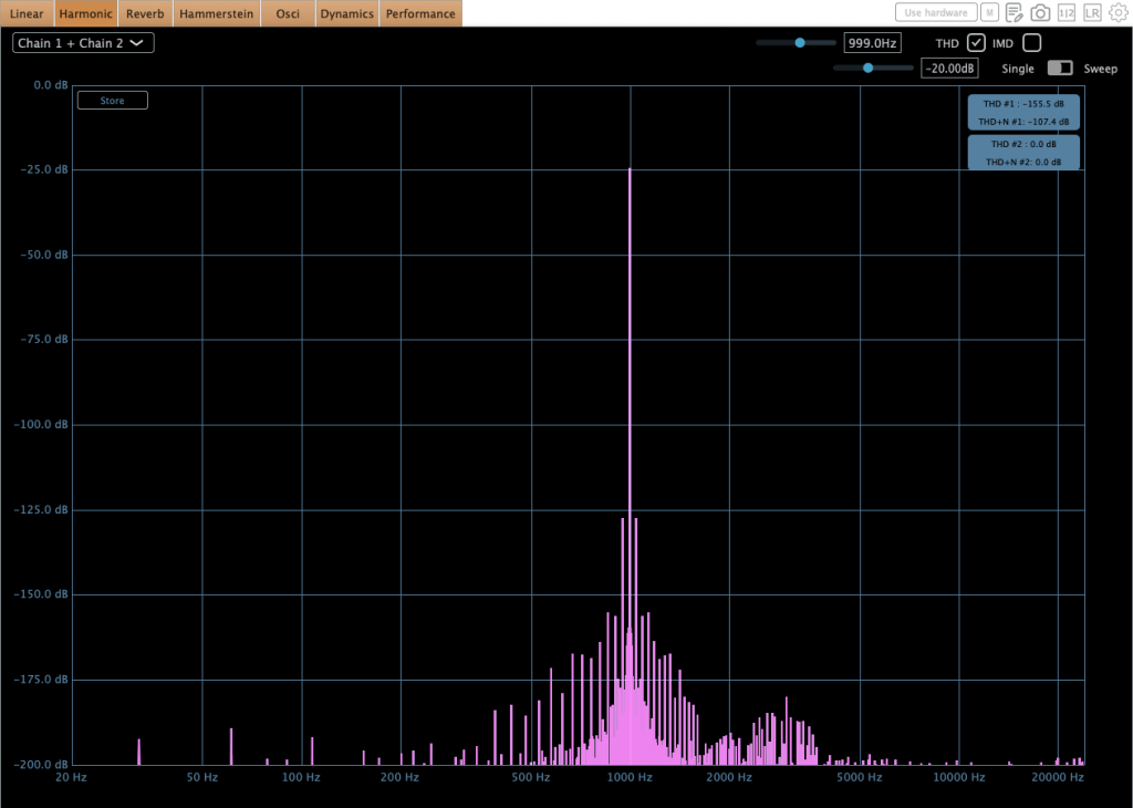
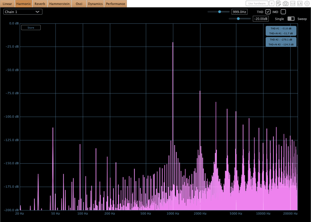
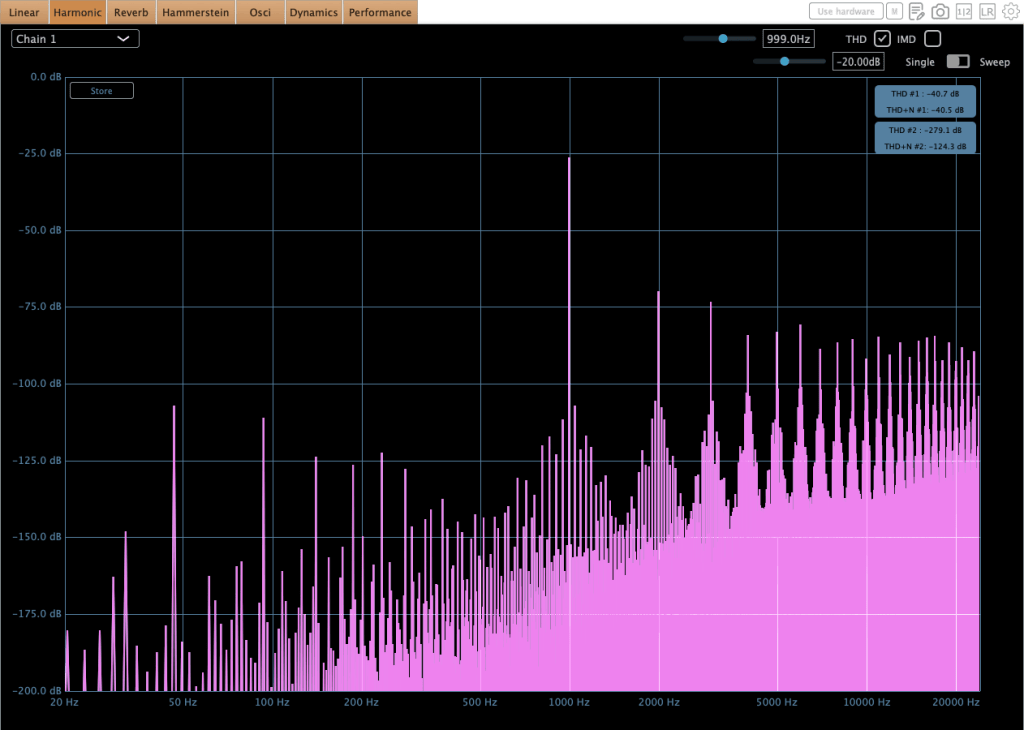
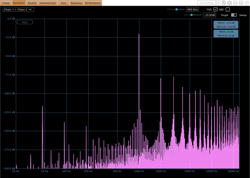
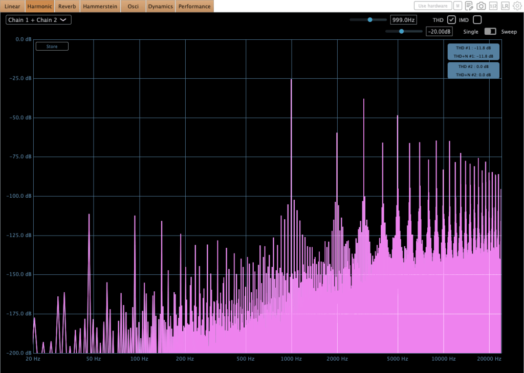
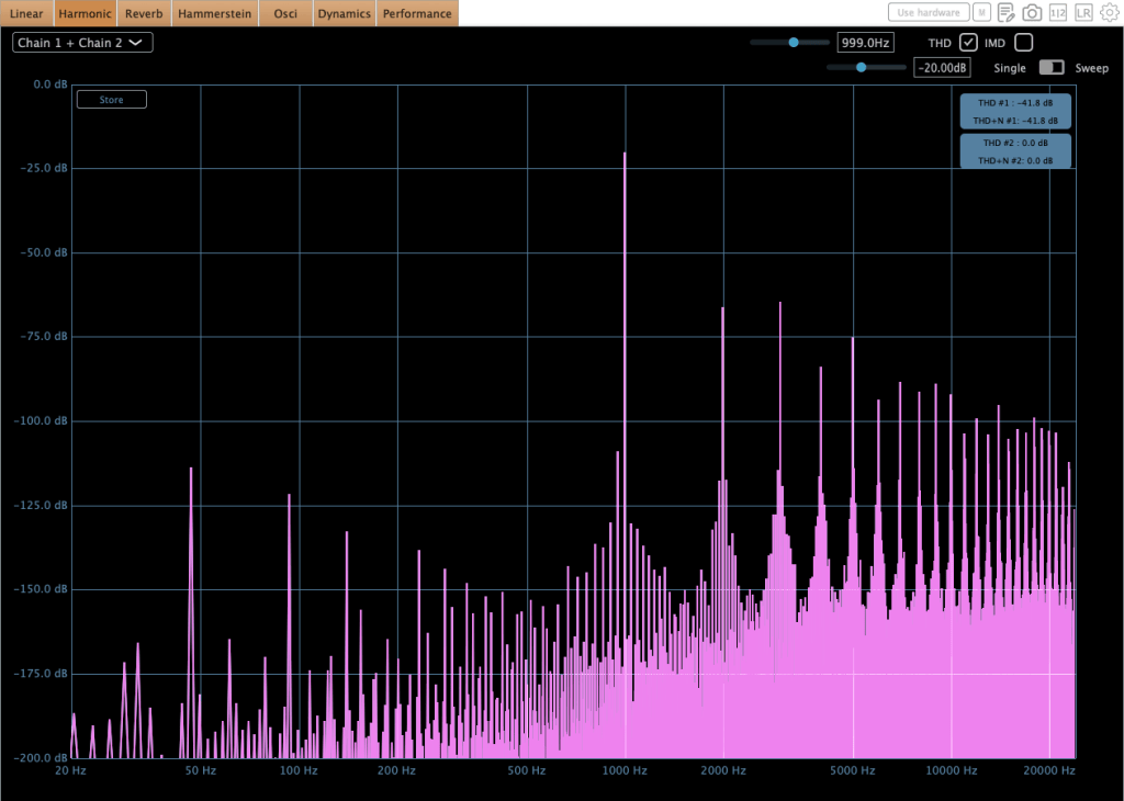
As shown in the image above, harmonic distortion levels are relatively low; however, they remain sufficient to noticeably alter the timbre of the sound.

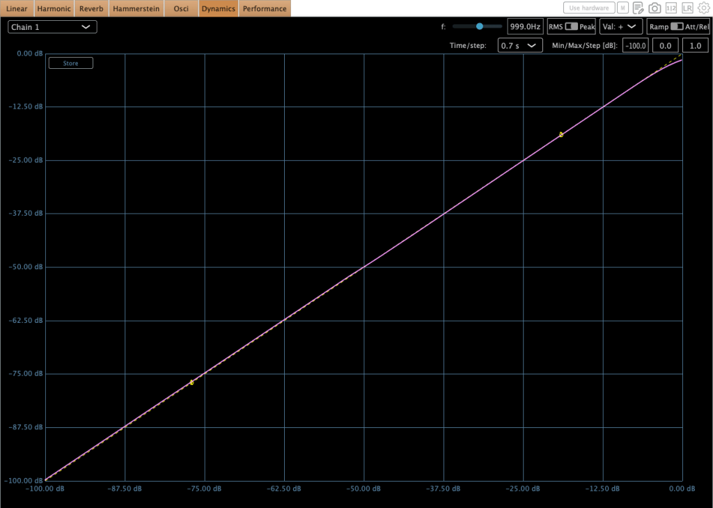
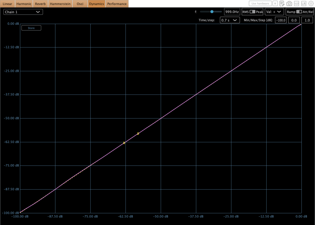
Compressor mode
Limiter mode

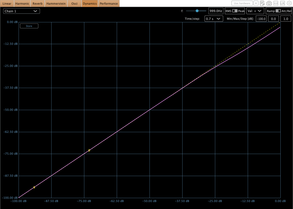
Regarding the compression curves, the unit provides a smooth transition in both modes; however, the Limiter mode utilizes a hard knee, whereas the Compressor mode employs a soft knee.

Compressor mode
Limiter mode

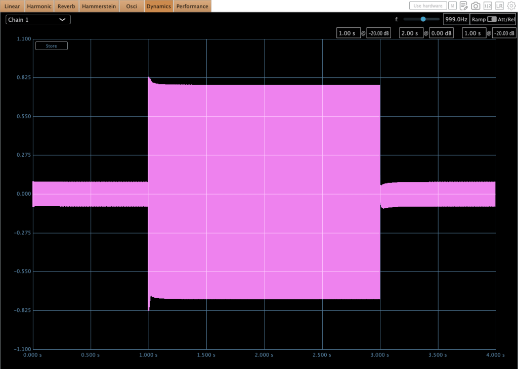
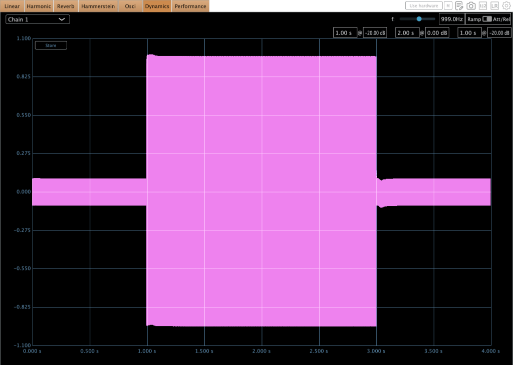
The images above illustrate the behavior of the unit in HIP mode

GR 2-3 dB
GR 1-2 dB

Furthermore, some peculiar behaviors occur during operation. Engineers typically target 0–2 dB of gain reduction on a mastering or mix bus compressor to achieve effective ‘glue.’ However, in this range, audible ‘pumping’ occurs. You can observe this specific behavior in the second photo above.

I encountered numerous discussions regarding this issue while researching the compressor prior to purchase. Although I anticipated the behavior, the audible effect was more critical than I had expected upon testing it myself.

Ultimately, I realized that the 0–2 dB gain reduction range is not ideal for this unit. Interestingly, pushing the gain reduction to 2–3 dB yields much better results, where the behavior stabilizes significantly in both compressor and limiter modes. This performance difference is illustrated in the first photo above.

It has a great sonic taste! It adds rich saturation and harmonic distortion across all frequency ranges, which fills out the empty spaces within the stereo field—a quality that is clearly audible.

However, because the character is so flavorful, I believe that applying a stereo imaging processor will help ‘release’ the sound that has become dense from the harmonic distortion, resulting in a more open and balanced result for mixing or mastering. To this end, I am looking forward to acquiring either an SPL Vitalizer MK3 or a Big Studio.

The unit features a 100 Hz high-pass filter with a 6dB per octave slope for internal signal detection, while also providing sidechain send/return inserts for external processing.

When the sidechain send/return inserts are connected, the internal detection circuit is bypassed, and the unit derives its detection exclusively from the external sidechain signal.

Therefore, a simple EQ connection is recommended for this function. To facilitate this, I am currently seeking a cheap used 1U rackmount EQ (like the Behringer FBQ1502HD) to utilize specifically with this sidechain insert.


Final Thought

It’s really great gear! I think it can be used in three ways:

  1. As a saturator: Running signals through the Manley Nu Mu without any gain reduction.
  2. For characteristic grooves: Using the sidechain function to create unique grooves with rhythmic signals.
  3. As a bus compressor: Using it for mixing or mastering.

I’ll be writing a follow-up post once I acquire an EQ or stereo imaging hardware for my setup. Thanks for reading! See you in the next post.

Advanced Synthesizers & Gear (2) – Eurorack Standard

Hello! This is Jooyoung Kim, an audio engineer and music producer. Today, I’ll talk about the most common standard of modular synthesizers, Eurorack.

These days, despite the appearance of many different kinds of synthesizers, a lot of people who make electronic music usually compose their songs with modular synthesizers.

In the past, every modular synthesizer company followed its own unique standards. Amid this chaos, the Eurorack format emerged by Doepfer Musikelektronik, in 1996 (especially Doepfer A-100) and eventually became the international standard for modular synthesizers.

This standard consists of two types of rules: physical and electrical.


Physical Rules

Behringer EURORACK GO

Height (3U): The standard height of all Eurorack modules is 3U (which is approximately 128.5 mm or 5.06 inches). This originates from the industrial rack unit standard.

Behringer EURORACK RACK

Width (HP): The width of a module is measured in HP (Horizontal Pitch).

  • 1 HP = 5.08 mm (0.2 inches).
  • A module’s width is always a multiple of this unit.

Mounting: Modules are secured to the case rails using M3 screws (M3 means that the diameter of the screw is 3mm).


Electrical Rules

IDC 16-pin ribbon cable

Power Supply (Voltage): Eurorack cases provide a bipolar power bus consisting of +12V, -12V, and Ground. Many modern systems also include a +5V rail to power digital modules. Modules draw this power via IDC ribbon cables:

  • 10-pin cables: Provide the standard power rails (+12V, -12V, and Ground).
  • 16-pin cables: Provide all the standard rails plus a +5V rail and optional CV/Gate bus lines for inter-module communication.

Patching (Signals): Modules communicate using 3.5 mm (1/8″) mono patch cables. These cables transmit both audio signals and Control Voltage (CV), allowing for a flexible, semi-permanent signal path.

Control Voltage (CV) Logic:

Arturia Keylab MK2 (in MK3, CV functions are disappeared)
  • Pitch (1V/Oct): The standard for controlling musical pitch is 1 Volt per Octave. This means that if you increase the control voltage by 1V, the pitch of the oscillator increases by exactly one octave.
  • Gate/Trigger: These are signals used to start or sync events.
Those electric signals are transmitted by 3.5mm TS cables.

In modular synthesizer systems, the concept of the sequencer is vital to composers. As I mentioned in my last article, Buchla-style synthesizers usually do not have keyboard-style controllers or interfaces. Therefore, they are mainly controlled by sequencer modules that include clock sync, gate/trigger, and pitch functions.

These sequencer modules can be connected to external keyboard controllers to achieve mutual clock synchronization, where either device can act as a master to drive the system’s tempo. Furthermore, many of these keyboard controllers can function as independent sequencers themselves, provided they include an integrated arpeggiator or built-in sequencing features.

I have Behringer Swing that includes CV functions. It’s really handy!

Therefore, if you intend to design sounds or compose music using Eurorack modules while requiring MIDI integration, you should choose a keyboard controller that supports these specific standards.

For instance, I have two keyboard-style midi controller that have CV functions, Behringer Swing and Arturia Keylab 61 mk2. Actually, I don’t have lots of modules or modular systems, but if I have to adapt to the external modular systems or plan to expand my own, having these connectivity options is a huge advantage.

Even if you don’t use them every day, these controllers offer a versatile bridge between your DAW and the Eurorack systems. While I personally use the Behringer Swing and KeyLab 61 MkII, there are other options like the Arturia KeyStep series or the Novation SL MkIII that serve the same purpose. They provide that link to modular gear without sacrificing the convenience of a standard MIDI controller, making them a good addition to a modern composing setup.


In practical usage, we need to talk about VCO (Voltage Controlled Oscillator), VCF (Voltage Controlled Filter), and VCA (Voltage Controlled Amplifier).

However, to explain those concepts need quite a lot of words. So, I’ll continue them in the next post!

By the way, I finally powered on my DIY hardware! However, the toroidal transformer is making a strange noise, and the amount of heat it is generating suggests there might be a problem with the circuit. I need to investigate what is causing this.

Even though I happily expect that I will be able to measure and add a final post about this hardware!

Also, I received a major revision decision on my new paper. There are quite a lot of required revisions, but that’s still great news for me.

Hmm..that’s all. See you in the next post!