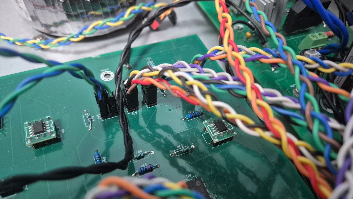
Hello, this is Jooyoung Kim, a mixing engineer and music producer.
Lately, I’ve been struggling with a few things like studying English for the TOEFL, preparing class materials, and conducting research. Among all these things, troubleshooting my tube saturator is the most convoluted work.
I wanted to post my article when I finished my build. However, since this continuous refinement makes it hard for me to write it, I’ve decided to document my progress step by step from now on.
Let’s start!
Main Problems
While fixing this machine, too many problems kept popping up. I’ve listed them below in the order they occurred:
- The unit wouldn’t power on, even though I flipped the power switch. -> resolved
- As soon as I powered it on, the toroidal transformer got so hot that it could fry an egg. -> resolved
- No output signals. -> resolved
- I found some issues with the meters. -> resolved
- One channel was muted, and a persistent white noise appeared. -> unresolved
- To fix the problem 5, adding capacitors made things worse. -> unresolved
So far, those are the steps I’ve taken. Therefore, I’ll explain each step chronologically.
The unit wouldn’t power on
It turned out to be just a cold solder joint. However, it was a real struggle to track down. While re-soldering everything, the problem still wasn’t solved. Then, I realized I hadn’t checked the solder joints on the power cord! Once I reflowed them, the power finally came on!
The toroidal transformer got so hot
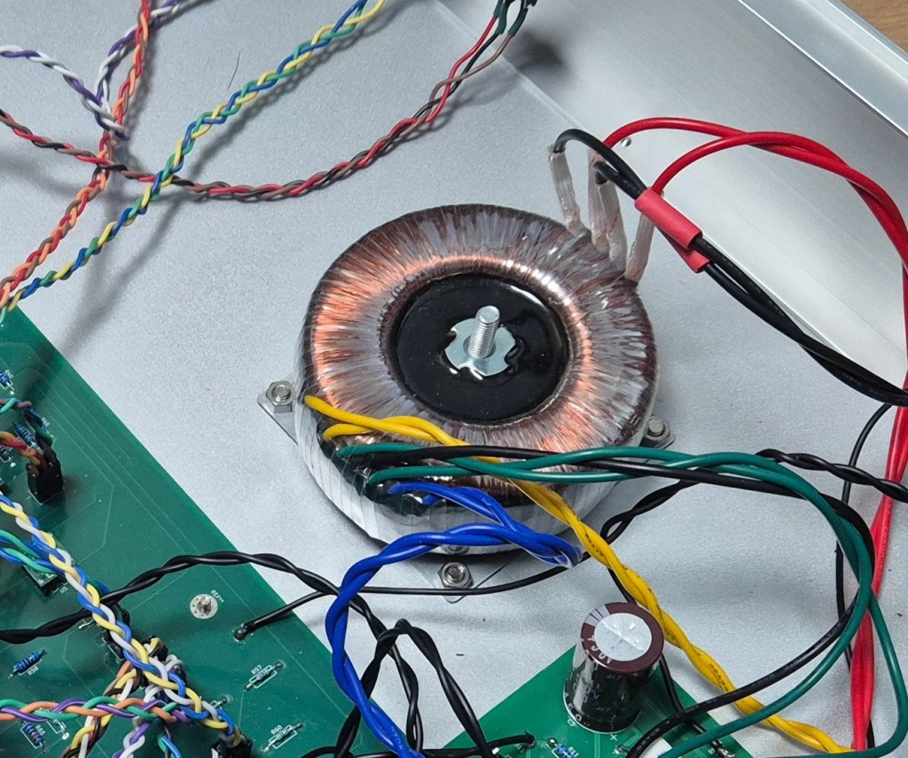
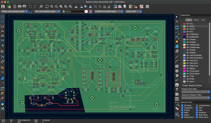
This problem stemmed from a design mistake. Specifically, the connection between the 0V line and GND caused the transformer to overheat. To fix this, I disconnected the line and insulated it with heat shrink tubing.
No output signals
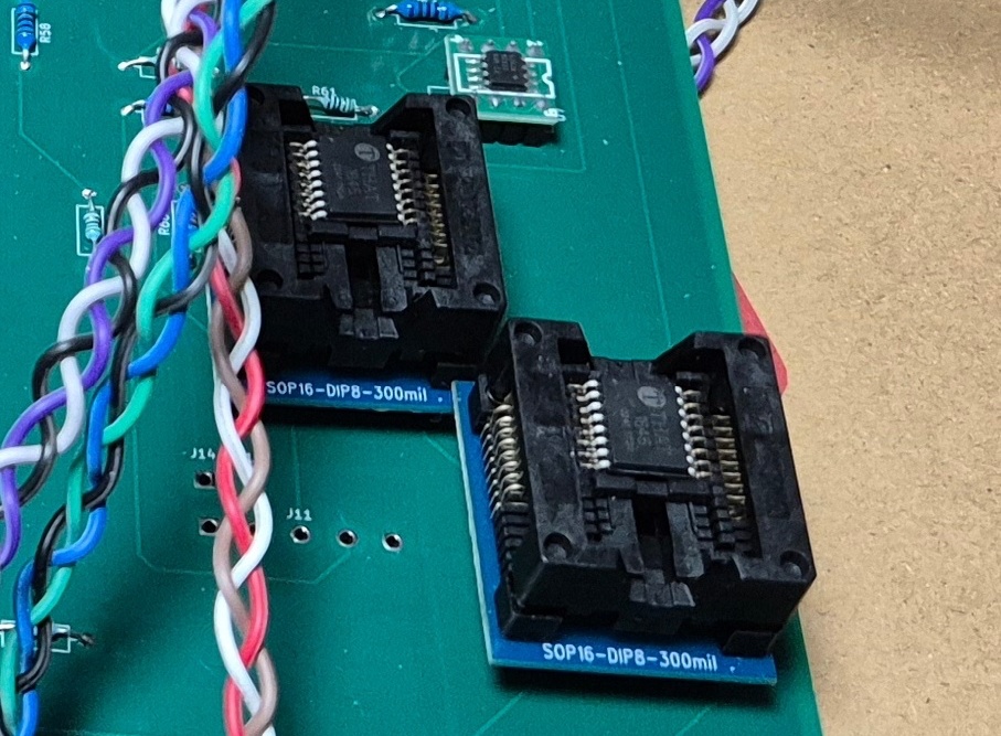
I figured that if I mounted the THAT1646 (SOP-16) onto an SOP-16 to DIP-8 breakout board, it would work. However, it turned out to be a completely wrong assumption. So, I ended up replacing all of them with DIP-8 standard devices.
Meter problems
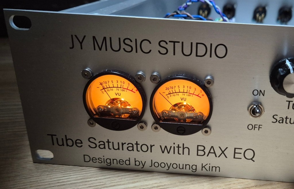
Once I finished soldering the entire circuit, I ran into three major issues with the meters:
- The right meter channel wasn’t working at all.
- Even though the meter circuit followed VU RMS standards, the ballistic response was way too fast.
- The audio signals were too hot, causing the needles to peg.
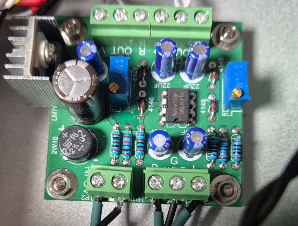
I found that the first problem was just a wiring mistake on my part.
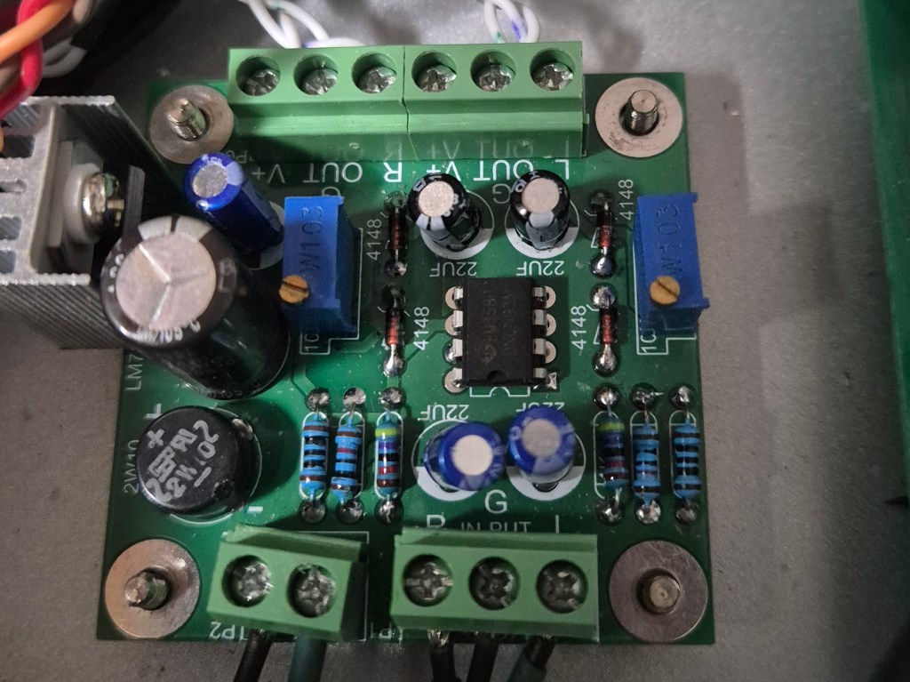
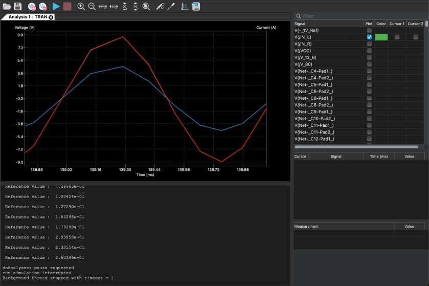
With a little help from Gemini and ChatGPT, I sorted out the second and third issues by feeding them the circuit text. It turns out the meter circuit was designed for -10 dBV (consumer audio level). To fix this, I swapped out a couple of resistors to pad down the input levels for both channels. As for the meter ballistics being too fast, I replaced the damping capacitors with higher-value ones to slow the needles down.
One channel was muted, and a persistent white noise appeared
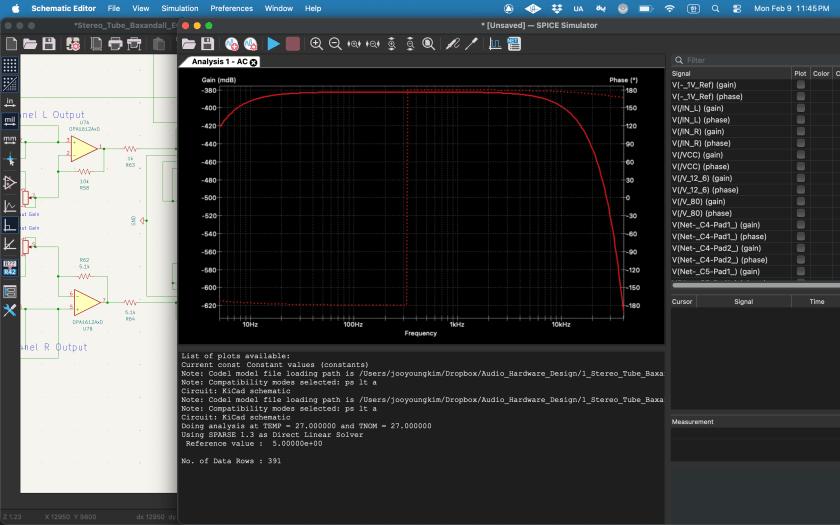
Yes… and this is the exact problem I’m still trying to sort out. Following ChatGPT’s advice, I added several decoupling capacitors to stabilize the power supply for the THAT1646 and OPA1612 chips.
At first, I misunderstood the advice and connected the capacitors in series with the supply voltage line and the chip pins. However, drawing on my background in physics, I realized that since it’s a DC power rail, connecting a capacitor in series didn’t make any sense. So, I double-checked the circuit configuration and finally realized it was a mistake.
To make matters worse, I totally messed up.
Honestly, I just needed to solder a few capacitors in parallel to the power rails. But instead, cluelessly overcomplicating things, I ended up desoldering all the chips and trying to install sockets.
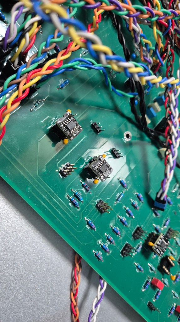
Since cleanly desoldering an 8-pin chip is an absolute pain, I just lost my patience and clipped the pins with nippers. Then I tried using square-pin headers, which didn’t fit into the sockets at all. So I had to order brand-new OPA chips, re-solder the pins, and wire up the capacitors in series again.
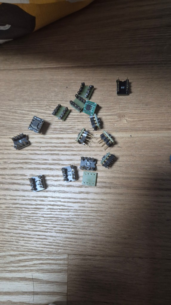
After going through all that self-inflicted hell, I finally tracked down some round-pin headers, re-soldered the chips properly, and got them plugged into the sockets.
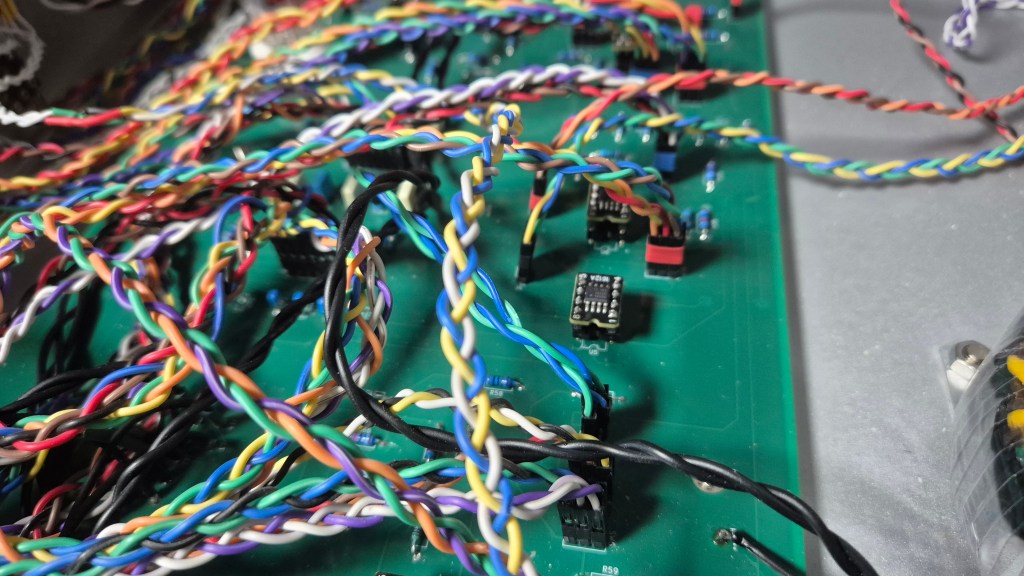
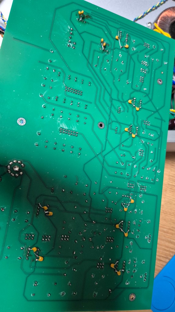
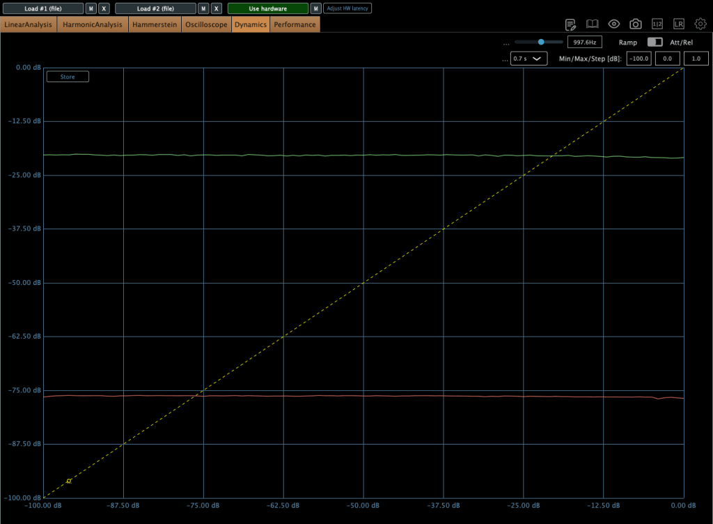
But guess what? Now, instead of music with some background noise like before, I’m getting pure, signal-driven noise blasting through. Ugh… hahahahahaha…haha…
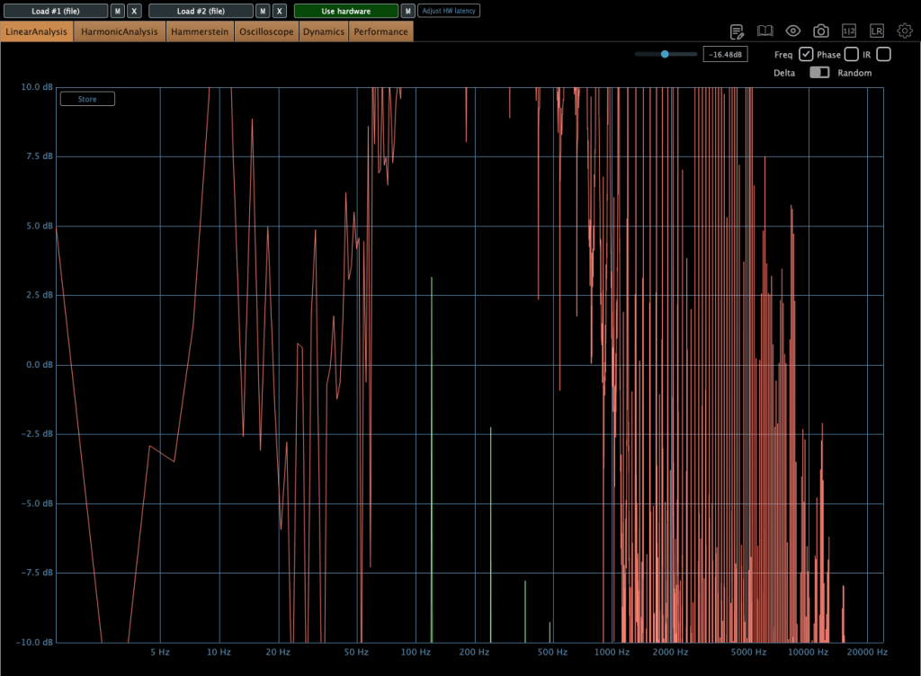
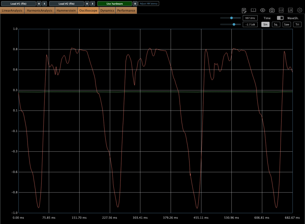
hahahahahahahahahahahahahahahah……ahaha..aaaaaa!!!!!!!
So yeah, this is the story of my troubleshooting journey so far.
While writing this post, I tried fixing a few more things last night. However, it turned out that my efforts were completely ineffective.
Juggling multiple things at once makes this feel like it’s dragging on forever, and I just want to wrap it up already. If all else fails, my last resort will be to rip everything out and wire it up on a fresh PCB… ugh. Trying to finish this all during break was definitely too ambitious.
See you in the next post!