Manley Nu Mu Stereo Limiter/Compressor Review

Hello! This is Jooyoung Kim, an audio engineer and music producer.

Now that the semester is over, I have a few weeks to rest and prepare materials for my next classes. Even so, I still have a lot of work to do on my new research, my DIY hardware projects, and my English studies. It will be very busy holidays.


By the way, recently, I decided that I need to sell my compressors, the Heritage Audio Successor and the Stam Audio SA-4000 MK2, and replace them with a mastering-grade compressor to mix and master music better.

Fortunately, last week I sold both of them, and I have been happily considering which mastering-grade compressor I should buy. There were several options to choose from, but I finally decided to buy the Manley Nu Mu Stereo Limiter/Compressor.

This decision came from my experience with the SPL IRON, the SPL Venos, and the Chandler Limited RS660 compressors, which are vari-mu-style compressors. They sound great across many genres, but they aren’t within my budget. (If I bought them, I’d have to live on cup noodles for about three months! :))

I also had an experience with the original Neve 33609/C compressor/limiter and the Chandler Limited EMI TG12413 Zener Limiter. These are diode-bridge compressors that have really great saturation; however, they are also unaffordable.

I found two reasonably priced compressors: the Rupert Neve Designs 5254 Shelford Diode Bridge Compressor and the Manley Nu Mu Stereo Limiter/Compressor. I ultimately chose the Manley because it was more affordable. Also, having previously owned a diode-bridge compressor—the Heritage Audio Successor—I was ready to explore a different style.

I was also attracted to the WesAudio ngBusComp, which features a handy digital recall system. However, it is a VCA-style compressor, which is the same type as the Stam Audio SA-4000 MK2 that I used to own.

Therefore, I decided to buy the Manley Nu Mu Stereo Limiter/Compressor!


Build Features

The Manley Nu Mu features eight knobs, six buttons, and two switches, excluding the power switch. The knobs (Threshold, Output, Recovery (Release), and Attack) and switches (Input Level) on the left side are identical to those on the right, allowing for independent adjustment of the left and right signals.

The Link button couples the left and right signal control knobs, with the notable exception of the Output controls. Consequently, these must be matched manually via measurement. Furthermore, apart from the Recovery knob, all controls feature continuous rotation, which makes precise recall of previous settings difficult.

The HIP (High Impact Preservation) control compresses quieter sounds while leaving loud peaks untouched. It processes these signals internally to achieve results similar to parallel compression. I found that the audio sounds more natural when engaged, so I may leave this button on permanently.

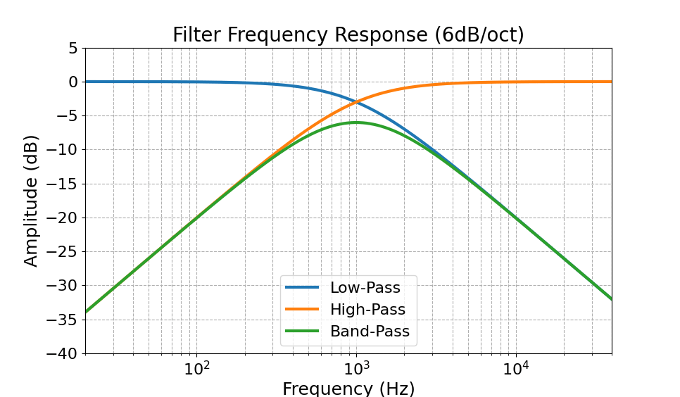
The HP SC (Sidechain High Pass Filter) button activates an internal filter with a 100Hz corner frequency and a 6dB/octave slope. This prevents the compressor from reacting to low-frequency energy below 100Hz, ensuring more stable gain reduction.


Measurments

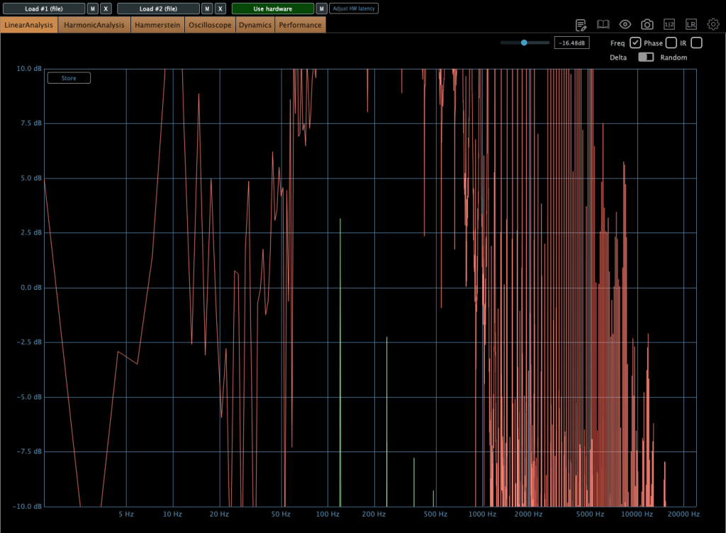
This equipment exhibits characteristic behaviors. Variations in input gain, threshold, attack time, and release time significantly affect the low-frequency response. Additionally, there is a slight amplitude discrepancy between the left and right circuits in the low end. This difference is easily observed in many compressors that do not naturally exhibit a low cut in their frequency response. For instance, when I demoed the SPL Venos, I found a significant discrepancy in the low-frequency output. Furthermore, an engineer peer of mine mentioned struggling with the same low-end inconsistency after purchasing an SPL Iron.

So, this level of discrepancy is acceptable.

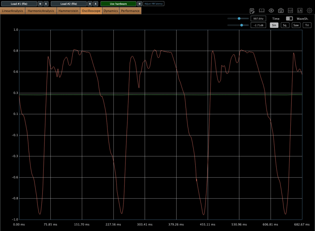
As shown in the image above, harmonic distortion levels are relatively low; however, they remain sufficient to noticeably alter the timbre of the sound.

Compressor mode
Limiter mode

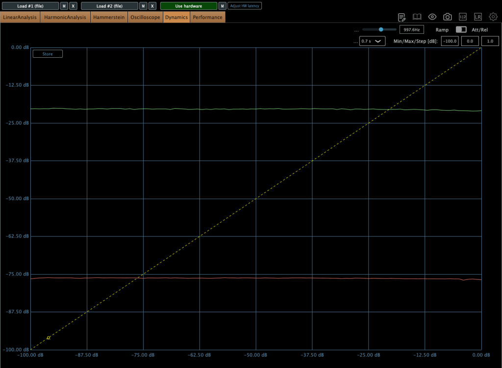
Regarding the compression curves, the unit provides a smooth transition in both modes; however, the Limiter mode utilizes a hard knee, whereas the Compressor mode employs a soft knee.

Compressor mode
Limiter mode

The images above illustrate the behavior of the unit in HIP mode

GR 2-3 dB
GR 1-2 dB

Furthermore, some peculiar behaviors occur during operation. Engineers typically target 0–2 dB of gain reduction on a mastering or mix bus compressor to achieve effective ‘glue.’ However, in this range, audible ‘pumping’ occurs. You can observe this specific behavior in the second photo above.

I encountered numerous discussions regarding this issue while researching the compressor prior to purchase. Although I anticipated the behavior, the audible effect was more critical than I had expected upon testing it myself.

Ultimately, I realized that the 0–2 dB gain reduction range is not ideal for this unit. Interestingly, pushing the gain reduction to 2–3 dB yields much better results, where the behavior stabilizes significantly in both compressor and limiter modes. This performance difference is illustrated in the first photo above.

It has a great sonic taste! It adds rich saturation and harmonic distortion across all frequency ranges, which fills out the empty spaces within the stereo field—a quality that is clearly audible.

However, because the character is so flavorful, I believe that applying a stereo imaging processor will help ‘release’ the sound that has become dense from the harmonic distortion, resulting in a more open and balanced result for mixing or mastering. To this end, I am looking forward to acquiring either an SPL Vitalizer MK3 or a Big Studio.

The unit features a 100 Hz high-pass filter with a 6dB per octave slope for internal signal detection, while also providing sidechain send/return inserts for external processing.

When the sidechain send/return inserts are connected, the internal detection circuit is bypassed, and the unit derives its detection exclusively from the external sidechain signal.

Therefore, a simple EQ connection is recommended for this function. To facilitate this, I am currently seeking a cheap used 1U rackmount EQ (like the Behringer FBQ1502HD) to utilize specifically with this sidechain insert.


Final Thought

It’s really great gear! I think it can be used in three ways:

  1. As a saturator: Running signals through the Manley Nu Mu without any gain reduction.
  2. For characteristic grooves: Using the sidechain function to create unique grooves with rhythmic signals.
  3. As a bus compressor: Using it for mixing or mastering.

I’ll be writing a follow-up post once I acquire an EQ or stereo imaging hardware for my setup. Thanks for reading! See you in the next post.

Advanced Synthesizers & Gear (2) – Eurorack Standard

Hello! This is Jooyoung Kim, an audio engineer and music producer. Today, I’ll talk about the most common standard of modular synthesizers, Eurorack.

These days, despite the appearance of many different kinds of synthesizers, a lot of people who make electronic music usually compose their songs with modular synthesizers.

In the past, every modular synthesizer company followed its own unique standards. Amid this chaos, the Eurorack format emerged by Doepfer Musikelektronik, in 1996 (especially Doepfer A-100) and eventually became the international standard for modular synthesizers.

This standard consists of two types of rules: physical and electrical.


Physical Rules

Behringer EURORACK GO

Height (3U): The standard height of all Eurorack modules is 3U (which is approximately 128.5 mm or 5.06 inches). This originates from the industrial rack unit standard.

Behringer EURORACK RACK

Width (HP): The width of a module is measured in HP (Horizontal Pitch).

  • 1 HP = 5.08 mm (0.2 inches).
  • A module’s width is always a multiple of this unit.

Mounting: Modules are secured to the case rails using M3 screws (M3 means that the diameter of the screw is 3mm).


Electrical Rules

IDC 16-pin ribbon cable

Power Supply (Voltage): Eurorack cases provide a bipolar power bus consisting of +12V, -12V, and Ground. Many modern systems also include a +5V rail to power digital modules. Modules draw this power via IDC ribbon cables:

  • 10-pin cables: Provide the standard power rails (+12V, -12V, and Ground).
  • 16-pin cables: Provide all the standard rails plus a +5V rail and optional CV/Gate bus lines for inter-module communication.

Patching (Signals): Modules communicate using 3.5 mm (1/8″) mono patch cables. These cables transmit both audio signals and Control Voltage (CV), allowing for a flexible, semi-permanent signal path.

Control Voltage (CV) Logic:

Arturia Keylab MK2 (in MK3, CV functions are disappeared)
  • Pitch (1V/Oct): The standard for controlling musical pitch is 1 Volt per Octave. This means that if you increase the control voltage by 1V, the pitch of the oscillator increases by exactly one octave.
  • Gate/Trigger: These are signals used to start or sync events.
Those electric signals are transmitted by 3.5mm TS cables.

In modular synthesizer systems, the concept of the sequencer is vital to composers. As I mentioned in my last article, Buchla-style synthesizers usually do not have keyboard-style controllers or interfaces. Therefore, they are mainly controlled by sequencer modules that include clock sync, gate/trigger, and pitch functions.

These sequencer modules can be connected to external keyboard controllers to achieve mutual clock synchronization, where either device can act as a master to drive the system’s tempo. Furthermore, many of these keyboard controllers can function as independent sequencers themselves, provided they include an integrated arpeggiator or built-in sequencing features.

I have Behringer Swing that includes CV functions. It’s really handy!

Therefore, if you intend to design sounds or compose music using Eurorack modules while requiring MIDI integration, you should choose a keyboard controller that supports these specific standards.

For instance, I have two keyboard-style midi controller that have CV functions, Behringer Swing and Arturia Keylab 61 mk2. Actually, I don’t have lots of modules or modular systems, but if I have to adapt to the external modular systems or plan to expand my own, having these connectivity options is a huge advantage.

Even if you don’t use them every day, these controllers offer a versatile bridge between your DAW and the Eurorack systems. While I personally use the Behringer Swing and KeyLab 61 MkII, there are other options like the Arturia KeyStep series or the Novation SL MkIII that serve the same purpose. They provide that link to modular gear without sacrificing the convenience of a standard MIDI controller, making them a good addition to a modern composing setup.


In practical usage, we need to talk about VCO (Voltage Controlled Oscillator), VCF (Voltage Controlled Filter), and VCA (Voltage Controlled Amplifier).

However, to explain those concepts need quite a lot of words. So, I’ll continue them in the next post!

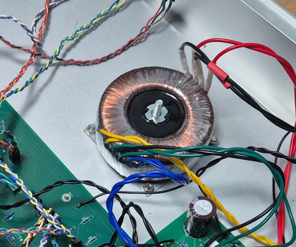
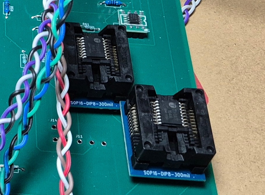
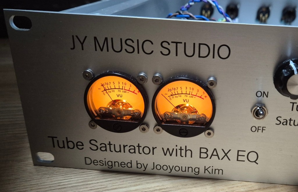
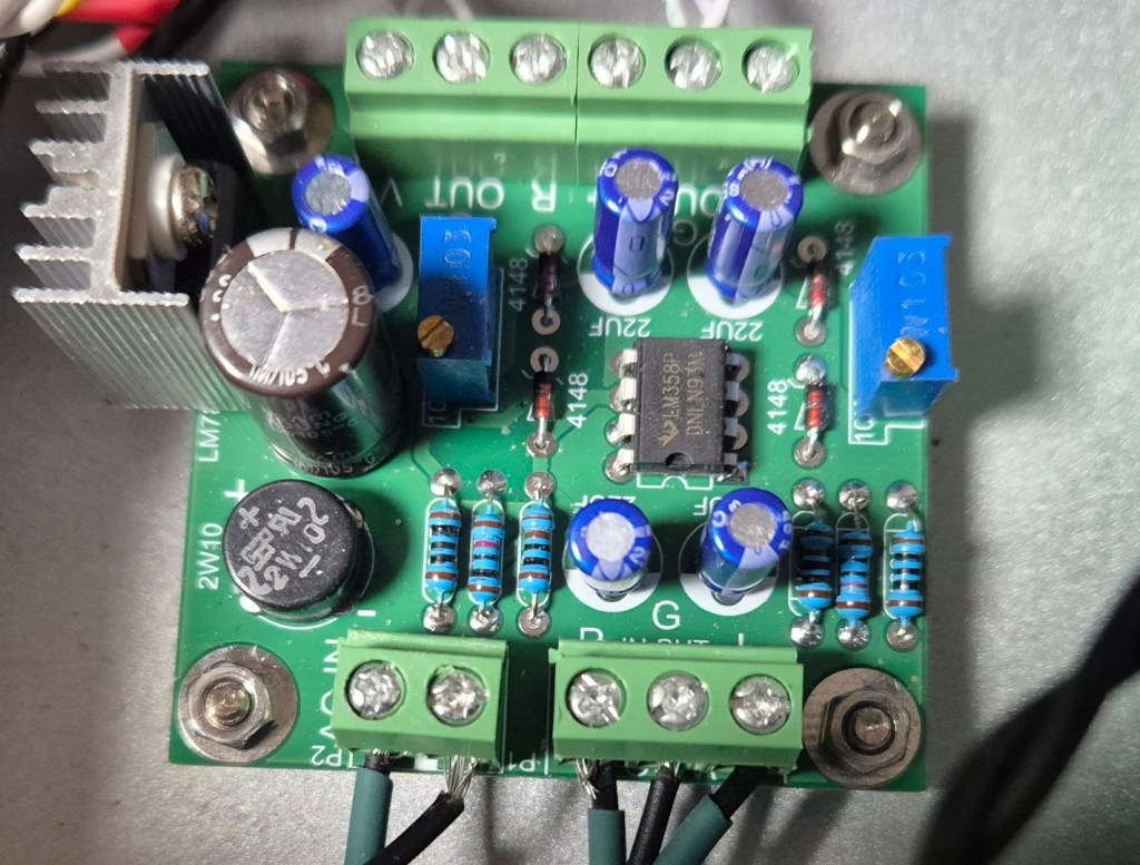
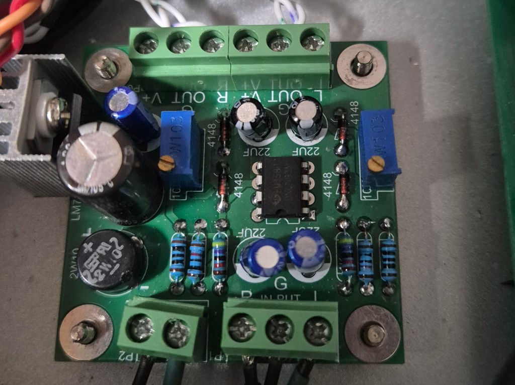
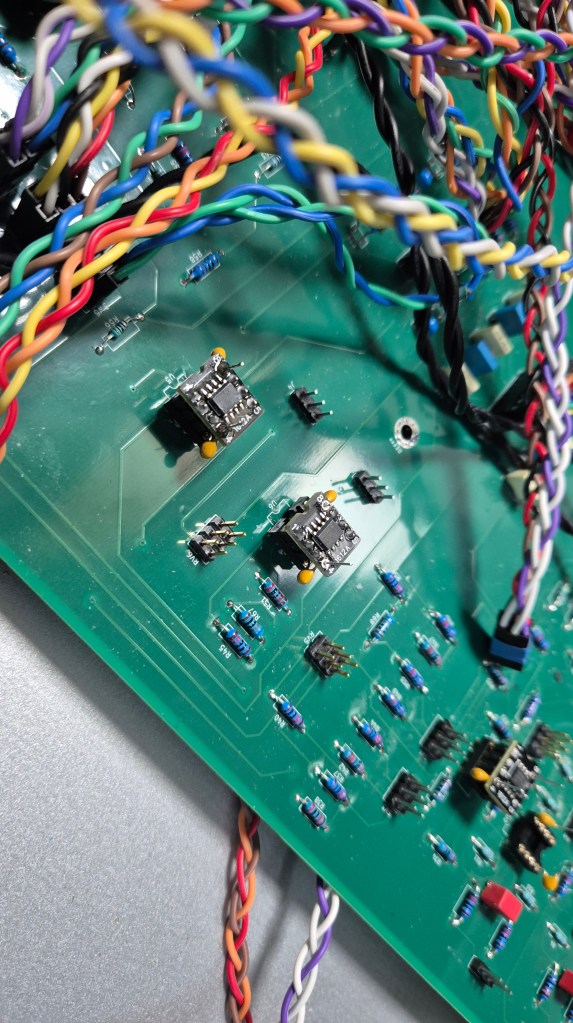
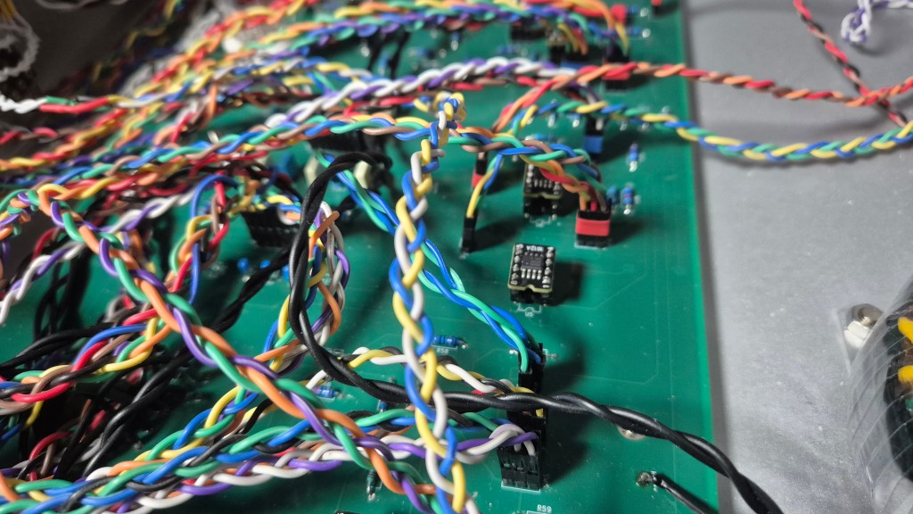
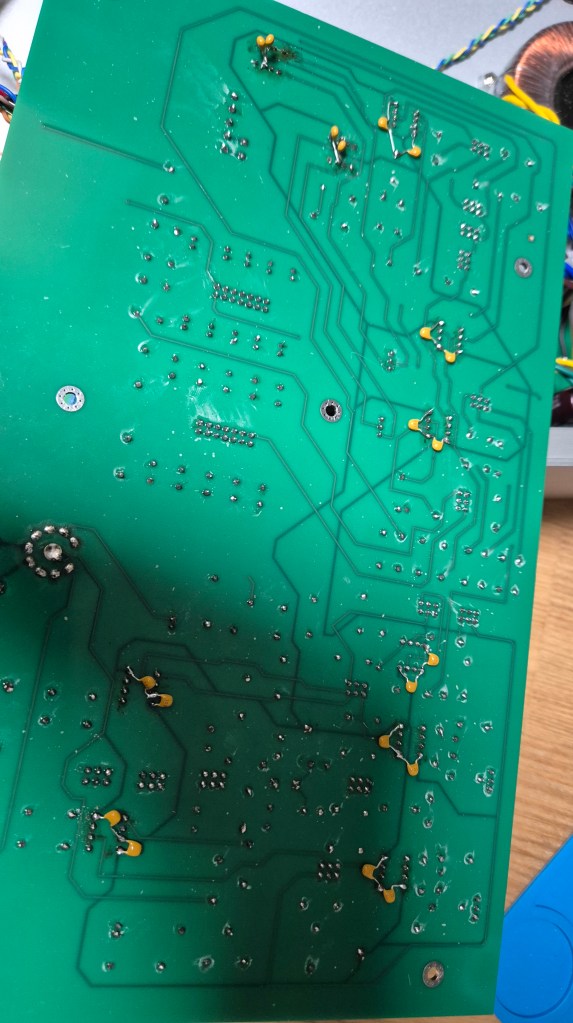
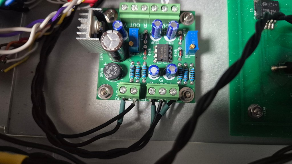
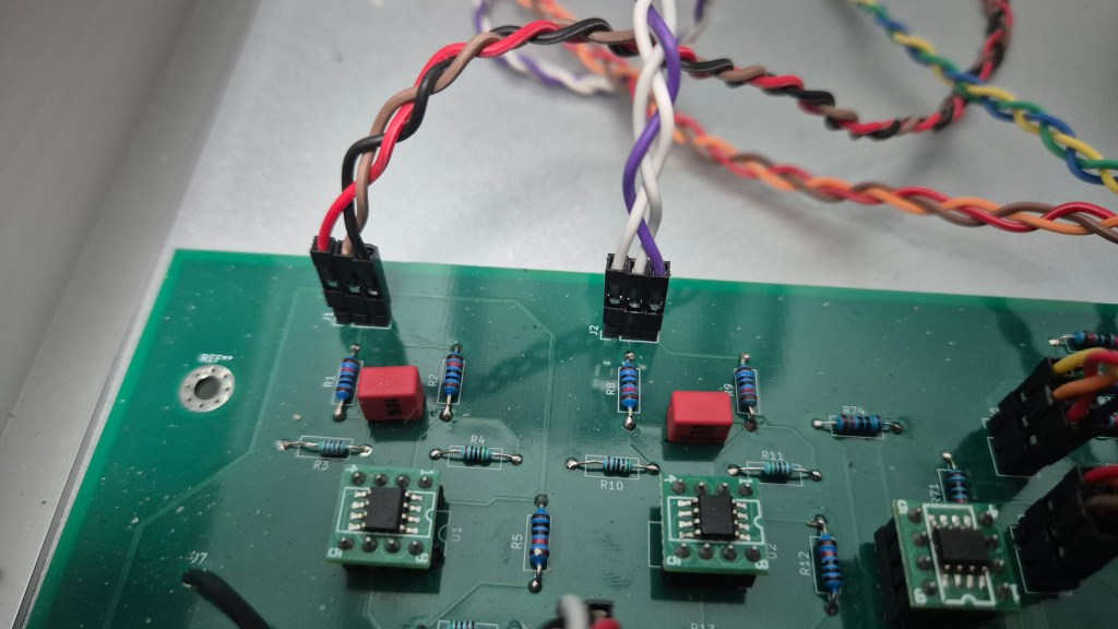
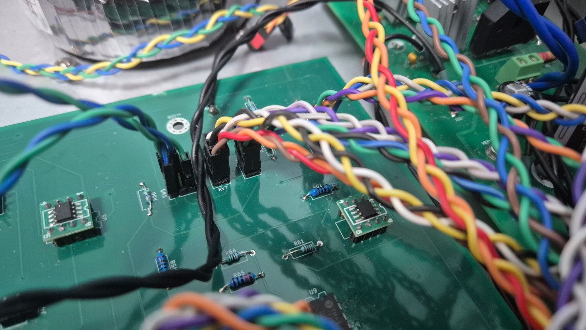
By the way, I finally powered on my DIY hardware! However, the toroidal transformer is making a strange noise, and the amount of heat it is generating suggests there might be a problem with the circuit. I need to investigate what is causing this.

Even though I happily expect that I will be able to measure and add a final post about this hardware!

Also, I received a major revision decision on my new paper. There are quite a lot of required revisions, but that’s still great news for me.

Hmm..that’s all. See you in the next post!
I Got an Accept Decision from the Journal of the Audio Engineering Society

Hello! This is Jooyoung Kim, an audio engineer and music producer.

Last week, thankfully I got an acceptance from the Journal of the Audio Engineering Society (JAES).

I’ve moved it to My Sent Mail folder so it doesn’t get mixed up with other emails.

Previously, I submitted my work to other journals like IEEE Transactions on Consumer Electronics, the Journal of the Acoustical Society of America, Applied Acoustics, and Signal Processing. Having gone through the process of rejection, I really appreciate this positive decision from the JAES. In fact, JAES has always been the journal I dreamed of publishing in the most, which makes this acceptance even more meaningful to me.

Initially, I was concerned that my idea was perhaps too simple, so I conducted an extensive review of existing research to see if it had already been addressed. To my surprise, I discovered that there was a lack of research specifically covering this simple approach.

Since the template was updated, I had to go through the process of rebuilding my PDF files in the editorial manager multiple times. The long list of submission records reflects the effort and patience required to get everything formatted just right.

The review process took quite a bit of time. I submitted my initial draft on December 11, received the revision decision on April 15, and finally, the acceptance on May 18. If the result had been a rejection, I would have been devastated, but given the significant workload of reviewers who dedicate their valuable time to evaluate others’ work, I was quite satisfied with this timeline.

However, as an independent researcher, I am entirely self-funded. I worked hard to condense my manuscript to stay within the 10-page limit for free publication, but I unfortunately exceeded it. Now, I have to cover the page charges myself. With the recent sharp rise in the exchange rate between the Korean won and the U.S. dollar, these additional costs have become quite a financial burden.

Despite the financial challenge, I am more than happy to pay this fee because JAES is the journal I have always aspired to publish in. Seeing my work accepted there is truly one of the most rewarding moments of my research journey.

Once my paper is officially published, I will write a follow-up post to explain the research in more detail. Stay tuned for the next update!

Advanced Synthesizers & Gear (1) – Harald Bode, Robert Moog, Don Buchla, and Dieter Doepfer

Hello! This is Jooyoung Kim, an audio engineer and music producer. Today, I’ll begin a new article series, Advanced Synthesizers & Gear.

In this series, we’ll talk about the history of modular synthesizers and the equipment. Also, we’ll figure out why famous synthesizers became so popular and how they work.

Before we focus on these topics, we need to know about the history of synths and how electricity can be turned into sound.

Let’s dive in!


Harald Bode

Harald bode, a German engineer and physicist(as a physics major myself, I feel a deep sense of kinship with Harald Bode), was a pioneer of the synthesizer.

He started a recording business, but soon ran into a major obstacle: the grand piano. At the time, recording technology was in its infancy compared to today, making it incredibly difficult to capture the true depth of the instrument.

Driven by this limitation, his inner physicist took over. Instead of trying to perfect the replication of acoustic instruments, he envisioned a completely new path—creating musical sounds 100% out of electronics using vacuum tubes. Guided by the physical principle that human voice timbres (Klangfarben) change based on the intensity of overtones, he laid the very foundation of modern synthesis by designing a system where parameters could be shaped with half-rotary knobs.

For those interested in exploring his technical blueprints and concepts firsthand, please look for his seminal 1961 publications: ‘European Electronic Music Instrument Design’ in the Journal of the Audio Engineering Society, and ‘Sound Synthesizer Creates New Musical Effects’ in Electronics magazine. Also you can see the bode’s equipment in eContact.

His groundbreaking concept of using voltage control to adjust parameters quickly spread through the pioneer community, deeply inspiring the figures who would go on to invent the world’s most iconic synthesizers: Robert Moog and Don Buchla.


Robert Moog

Robert Moog also majored in Physics during his undergraduate years, earning his Bachelor of Science from Queens College in 1955 before completing a PhD in Engineering Physics at Cornell University. With this background, Moog approached electronic music through a technological lens very similar to Harald Bode’s.

In the fall of 1960, at the Audio Engineering Society (AES) convention in New York, Moog attended Harald Bode’s presentation of his modular ‘Audio System Synthesizer’. At this convention, Bode demonstrated the concept of using voltage control to manipulate audio parameters within a modular architecture.

Following this exposure to Bode’s design, Moog set out to develop a compact, practical synthesizer for musicians, contrasting with the room-sized systems of the era like the RCA Mark II. While previous instruments relied on hundreds of vacuum tubes, Moog utilized newly available silicon transistors, leveraging the exponential relationship between input voltage and output current.

Moog Minimoog

This application of transistor physics led to his principal innovation in 1964: the Voltage-Controlled Oscillator (VCO). While Bode established the foundational concept of altering parameters via voltage, Moog engineered the precise circuitry that mapped input voltage to specific musical intervals. Through this hardware, Moog standardized fundamental synthesizer concepts, including modularity, envelope generation, and the pitch wheel.

Moog viewed his role primarily as a toolmaker for artists rather than a corporate businessman, choosing not to patent core innovations like modularity or voltage control.


Don Buchla

Interestingly, the application of physics to modular synthesis was not confined to Harald Bode and Robert Moog. Donald Buchla, another pioneer who co-invented the voltage-controlled modular synthesizer independently during the early 1960s, also graduated as a physics major from the University of California, Berkeley, in 1959.

In 1962, Buchla formed his company, Buchla and Associates, in Berkeley. He was commissioned by composers Morton Subotnick and Ramon Sender of the San Francisco Tape Music Center to create an electronic instrument tailored for live performance. Guided by this request, Buchla began designing his first modules in 1963.

Buchla Skylab

While Robert Moog was developing his system on the East Coast, Buchla was working independently on the West Coast. In 1965, utilizing a grant from the Rockefeller Foundation, he assembled these modules into the Buchla Modular Electronic Music System (later known as the Series 100), which entered commercial production in 1966.

Like Moog, Buchla utilized voltage control as the core mechanism to alter audio parameters. However, his approach to user interfaces and musical philosophy differed significantly. While Moog standardized the traditional piano-style keyboard to make the instrument accessible to conventional musicians, Buchla deliberately rejected the keyboard, viewing it as a limitation carried over from acoustic history. Instead, he pioneered alternative control interfaces, such as touch-sensitive plates that allowed for non-traditional, expressive manipulation of voltage.


Because these two distinct styles of synthesizers were developed independently based on the geographical regions where their creators worked, Moog’s system became known as the East Coast style, while Buchla’s was termed the West Coast style.


Doepfer

The historical lineage of physics-driven modular synthesis culminated in the late 20th century with the establishment of the Eurorack standard. Developed in 1995 by Dieter Doepfer, the founder of Doepfer Musikelektronik, Eurorack solved a critical fragmentation problem in the modular synthesizer market. Like Bode, Moog, and Buchla before him, Doepfer formally studied physics, beginning his academic training at Munich in 1972.

Doepfer’s entry into hardware development was directly influenced by his background in physics. While completing his mandatory community service in the ophthalmology department of a Munich hospital, Doepfer utilized the department’s dedicated electronics laboratory—originally built for laser eye surgery research—to quietly develop his earliest synthesizer circuits. This research resulted in his first complete system, the Polyphonic Module System (PMS), released as a DIY kit.

Throughout the 1980s, Doepfer continued to expand his technical expertise. He integrated specialized integrated circuits (ICs) from Curtis Electronic Music Specialties (CEM) to build highly efficient analog systems, and later adapted to the digital transition by developing 8-bit sampler cards and MIDI master keyboards. However, the commercial market shifted during the 1990s; a resurgence of interest in analog synthesis led to the unexpected success of his MS-404 monophonic synthesizer in 1994, which prompted high demand for expanded modular options.

To address this demand systematically, Doepfer introduced the A-100 system in 1995, establishing the Eurorack format. Prior to this, systems by Moog or Buchla used incompatible dimensions and electrical standards. Doepfer unified the ecosystem by introducing open, standardized physical and electrical specifications:

  • Physical Dimensions: Height was set using the sub-rack unit standard at 3U (approx. 128.5 mm), and width was measured in HP (Horizontal Pitch), where 1 HP equals 0.2 inches (5.08 mm).
  • Electrical Connectivity: Power was distributed via standardized ribbon cables supplying ±12V DC.
  • Signal Interface: Control Voltages (CV) were routed using compact 3.5mm mini-jacks rather than the bulky 1/4-inch or banana jacks of earlier decades.

By keeping this format open, Doepfer created a universal framework that allowed third-party manufacturers and boutique designers to build compatible components. His designs even attracted pioneers of the genre; Florian Schneider of Kraftwerk collaborated with Doepfer to modify hardware for speech synthesis triggering, a relationship that later influenced the development of the MAQ 16/3 MIDI analog sequencer.

Through these modular standards, Eurorack transformed synthesis from a market of isolated, proprietary hardware into a decentralized, global ecosystem.

Furthermore, because this standard has become so widespread, even non-Eurorack standalone hardware instruments often feature compatible 3.5mm patching connectors. Thanks to this universal connectivity, users can cross-connect entirely different, independent synthesizers to act as interlinked sub-components—such as routing one synthesizer’s output to serve purely as an oscillator, bypassing into another instrument’s filter, or patching through separate external units for saturation and effects.

I will explain the technical details and creative mechanics of these Eurorack modular synthesizers in a later post.

See you then!